Controller board removal
CAUTION—SHOCK HAZARD: After disconnecting the high-voltage power cable from the controller board,
always check that the HVPS connection was not loosened. Make this check anytime you are working near the
HVPS cable.
Warning—Potential Damage: Observe all ESD precautions while handling electrostatic discharge sensitive parts. See
Handling ESD‑sensitive parts on page 4‑1.
Warning—Potential Damage: Replace one of the following components, and perform a POR before replacing a
second component. Never replace both of the components without performing a POR after installing each one, or
the printer may be rendered inoperable:
• UICC
• Controller board
Warning—Potential Damage: Never install and remove components listed above as a method of troubleshooting
components. Once one of these components has been installed in a printer, and the printer is powered on, the
component cannot be used in another printer. The component must be returned to the manufacturer.
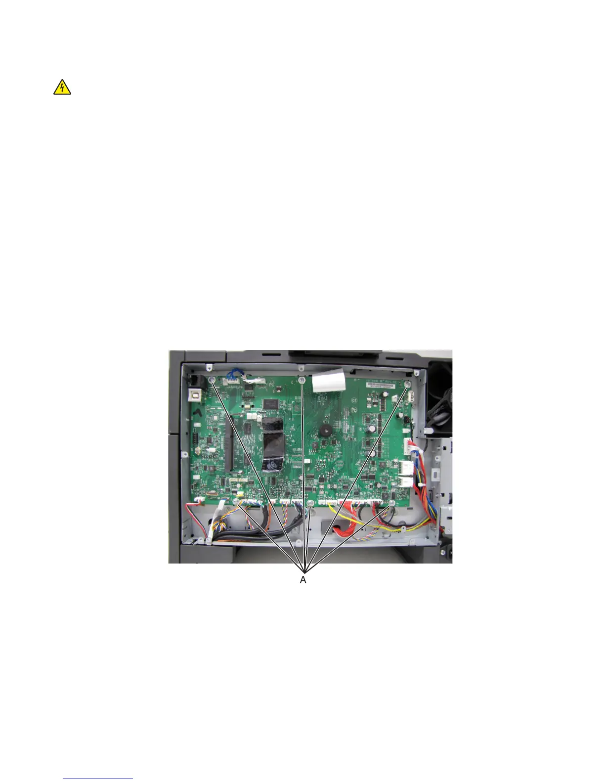
1 Remove the rear cover. See “Rear cover removal” on page 221.
2 Disconnect all cables from the controller board, and remove the six screws (A).
Note: To prevent damage, do not use tools when disconnecting the ribbon cables from JPH1 and JLCD1 on the
controller board.
7527
Repair information
239