OPERATING PROCEDURES GRT8120 OPERATOR MANUAL
4-126 Published 3-22-2021, Control # 702-02
Defining Subsequent Virtual Walls
To define and enable further Virtual Walls (such as Virtual
Walls 2 through 5), the following steps can be used:
1. Be sure you are on the Virtual Walls Limitation Screen
Icon (7, Figure 4-113).
2. Use the Right Arrow (4, Figure 4-62) function key to
highlight the Virtual Wall Number Item (1, Figure 4-113).
3. If the wall number shown is not the correct number for
the new wall (note that it increments automatically when
the previous wall was defined). Use an OK Button
(5, Figure 4-62) to allow modifying the value. Use the
Up/Down Arrow Keys (4, Figure 4-62) to alter the Virtual
Wall number to the desired value. Use an OK Button
(5, Figure 4-62) to finish entering the value.
4. Position the crane so that the hook is located at the
position to define the first point of the Virtual Wall (Point
A or Item 2) as shown in Figure 4-113.
5. Use the Right Arrow (4, Figure 4-62) Function key to
highlight the Accept Crane Position Point A Symbol
(2, Figure 4-113).
6. Use an OK Button (5, Figure 4-62) to accept the current
crane position to be Point A as shown in Figure 4-113.
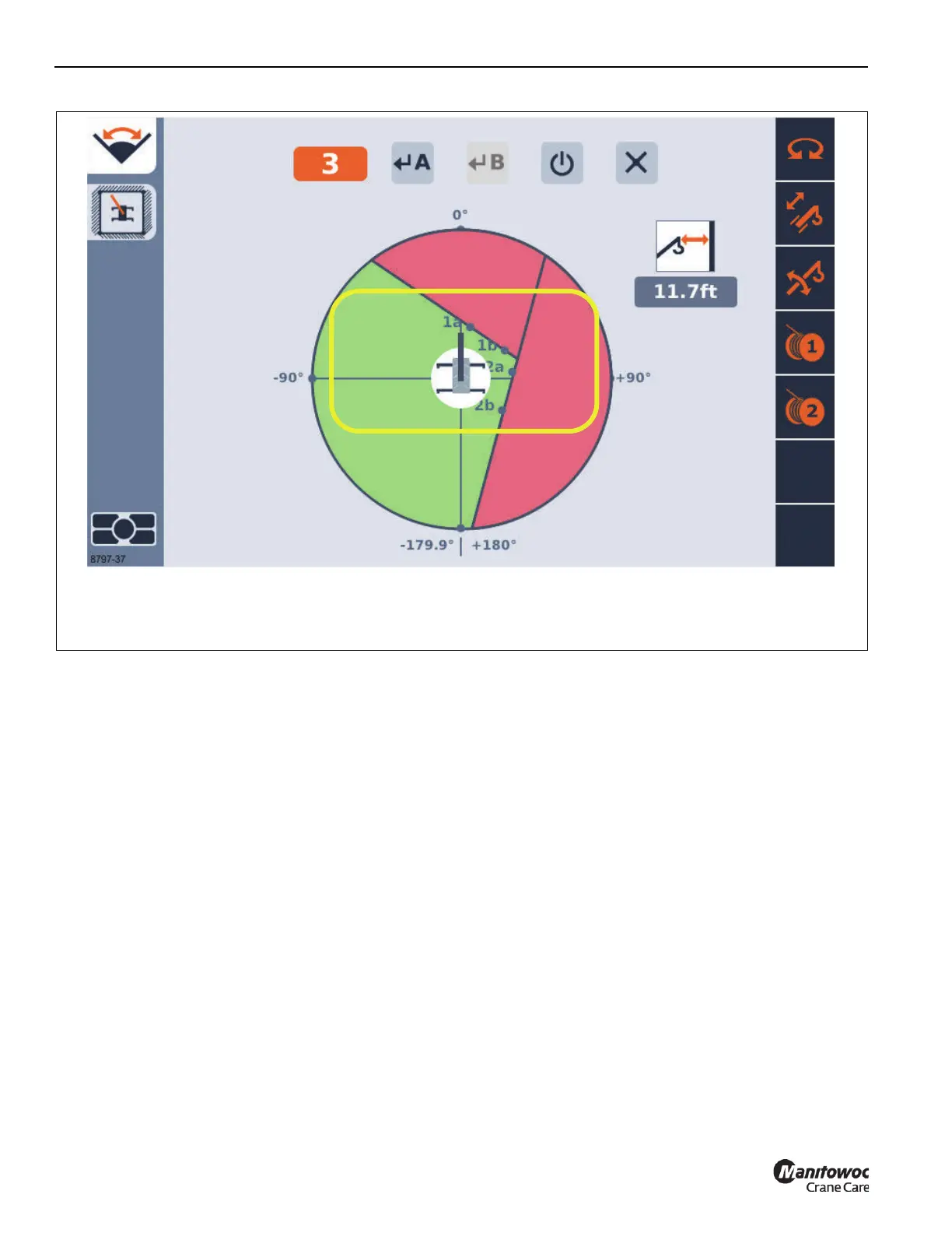
The location of the point should now be shown on the
screen with a label that shows the wall number and the
letter 'a' as shown in the yellow highlight in the sample
Figure 4-114.
7. Position the crane so that the hook is located at the
position to define the second point of the Virtual Wall
(Point B or Item 3), (Figure 4-113).
NOTE: The 2 points may not be so close to each other that
a virtual wall is not clearly defined; the 2 points
should be at least 10 ft apart.
8. Use the Right Arrow (4, Figure 4-62) Function key, if
needed, to highlight the Accept Crane Position Point B
Item (3, Figure 4-113).
9. Use an OK (5, Figure 4-62) Button to accept the current
crane position to be Point B (3, Figure 4-113). The
location of the point should now be shown on the screen
with a label (1b) as shown in yellow highlight in
Figure 4-114.
NOTE: The screen should also show another “forbidden
zone” for the area beyond the Virtual Wall. Use a
visual inspection of the screen and the area around
the crane to verify that the Virtual Walls are
providing the desired zone correctly. Again, note
FIGURE 4-114
8797-37
Virtual Walls Limitation Screen with 2 Virtual Walls already active
EXAMPLE ONLY- Display Values May Vary

 Loading...


