Grove Published 3-22-2021, Control # 702-02 5-43
GRT8120 OPERATOR MANUAL SET-UP AND INSTALLATION
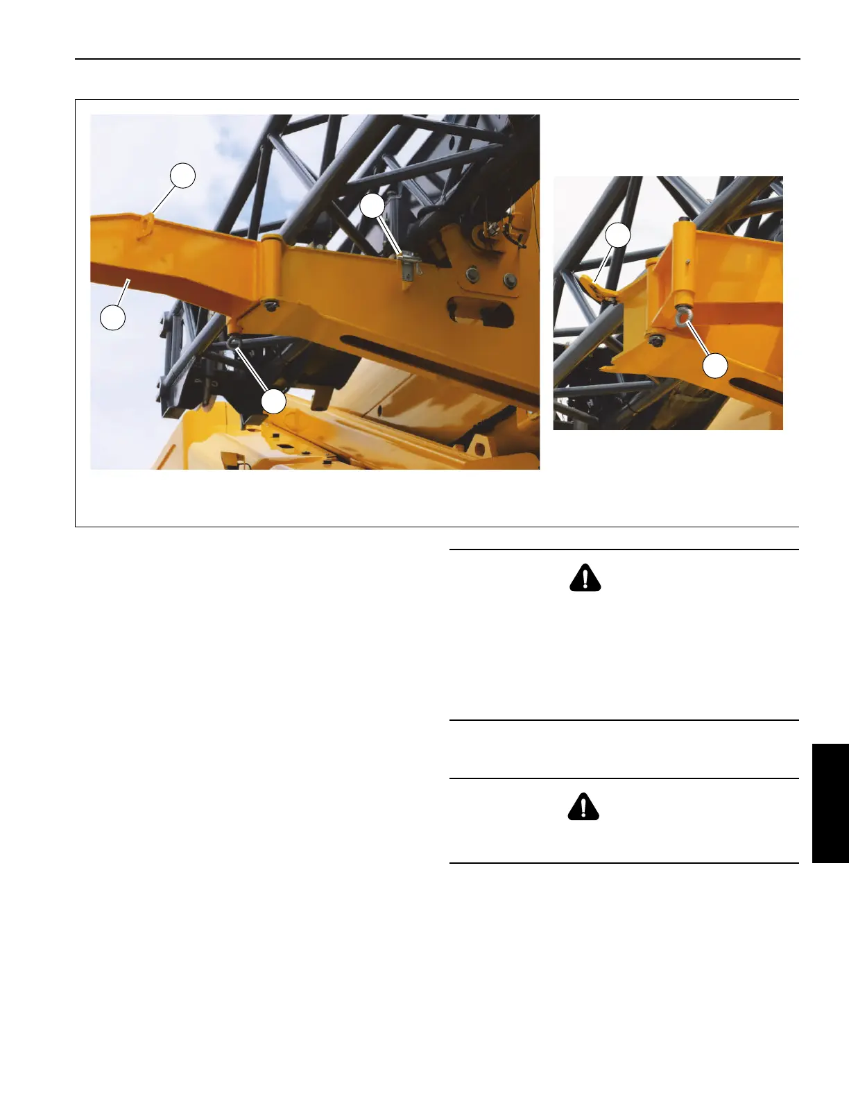
5. Make sure rear boom extension ramp (3, Figure 5-64) is
in erected position.
If the ramp is not erected, retract the retaining pin (1)
from the bracket (2) to release the rear boom extension
ramp (3) from the stowed position. Fully swing the rear
boom extension ramp (3) into the erected position. Make
sure the pin (4) locks into position on the rear boom
extension bracket (5).
6. Unreeve the hoist rope as necessary from the boom
extension base section mast sheaves. For more
information, see Unreeving Hoist Rope, page 5-55.
7. If necessary, stow the fly section. For more information,
see Stowing the Fly Section, page 5-41.
8. Remove the anti-two block switch from the end of the
boom extension. For more information, see Anti-Two
Block Switch on the Boom Extension, page 5-58. Install
the anti-two block switch on the auxiliary boom nose. For
more information, see Anti-Two Block (A2B) Switch,
page 5-10.
9. Stow the mast sheave assembly. For more information,
see Folding Mast Sheave, page 5-59.
10. Attach a tag line to the end of the boom extension base
section.
11. Make sure the boom extension installation pins
(4, Figure 5-39) are engaged.
12. Remove the four pins (5, Figure 5-39) and retaining clips
(6) that attach the boom extension base section to the
boom nose. Store the pins (5) and retaining clips (6) on
the boom extension stowage bracket.
FIGURE 5-64
Deployed
10088-8a
1
2
3
4
Stowed
4
5
10088-9a
DANGER
Boom Extension Hazard!
The boom extension installation pins (4, Figure 5-39)
must be extended and engaged before removing the four
pins (5, Figure 5-39). If the boom extension installation
pins (4, Figure 5-39) are not extended and fully engaged,
the boom extension will fall when pins (5, Figure 5-39) are
removed, resulting in possible injury or death.
CAUTION
After removing the four retaining clips and pins, the boom
extension is free to swing to the side of the main boom.

 Loading...


