5-50 Published 3-22-2021, Control # 702-02
SET-UP AND INSTALLATION GRT8120 OPERATOR MANUAL
b. Press and hold the OK on the ODM navigation pad
or press down on the jog dial.
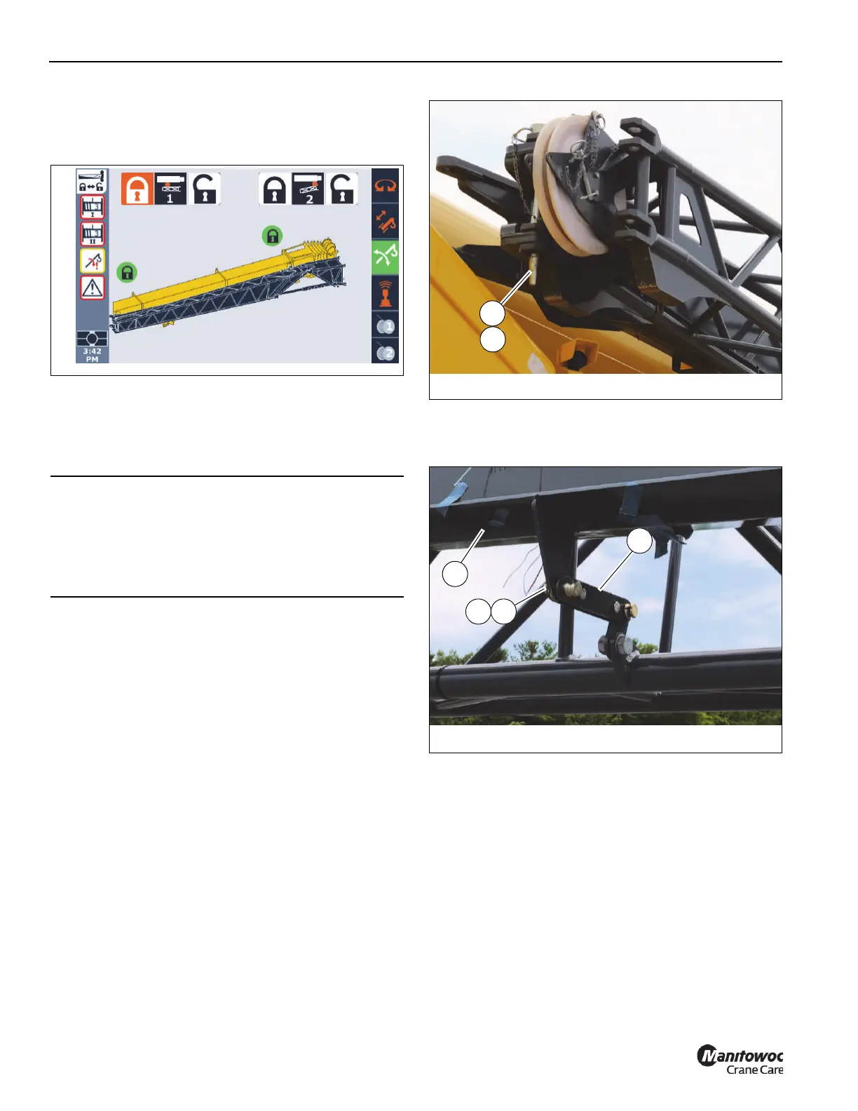
When front extension pin is locked, the status
indicator show a green lock icon.
15. Visually confirm that the front boom extension pin (Pin
#2 in the ODM) is locked. The handle should be in the up
position. When the handle is in the up position, the front
mounting pin is extended and the boom installation pins
are unlocked.
16. Turn the jack screw (3, Figure 5-39) counterclockwise
with the impact wrench and extension to retract the
boom extension installation pins (4) from the boom
nose.
17. Move the boom extension to the fully stowed position.
18. Remove the pin from its holder on the boom extension
base section. Attach boom extension base section to fly
section by installing the pin (2, Figure 5-70) and
securing it with the retaining clip (1).
19. Attach the fly section to the boom extension base
section using the connecting link (1, Figure 5-71).
Secure connecting link with pin (3) and retaining clip (2).
20. Disconnect electrical connections. For more information,
see Boom Extension Electrical Connections, page 5-51.
21. If stowing a hydraulic boom extension, disconnect
hydraulic connections. For more information, see
Hydraulic Boom Extension Connections, page 5-52.
DANGER
Crush Hazard
To avoid death or serious injury, make sure the front
mounting pin (Pin #2) is installed and the handle
(1, Figure 5-35) is locked prior to retracting the boom
extension installation pins (4, Figure 5-39).
FIGURE 5-71
10088-11a
1
2 3
4

 Loading...


