McHale Fusion 2 electronic control system section
11- 16
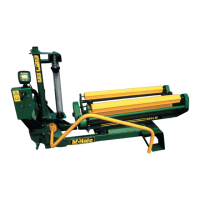
McHale Fusion 2 round baler wrapper technical service manual
Issue 1: 0208
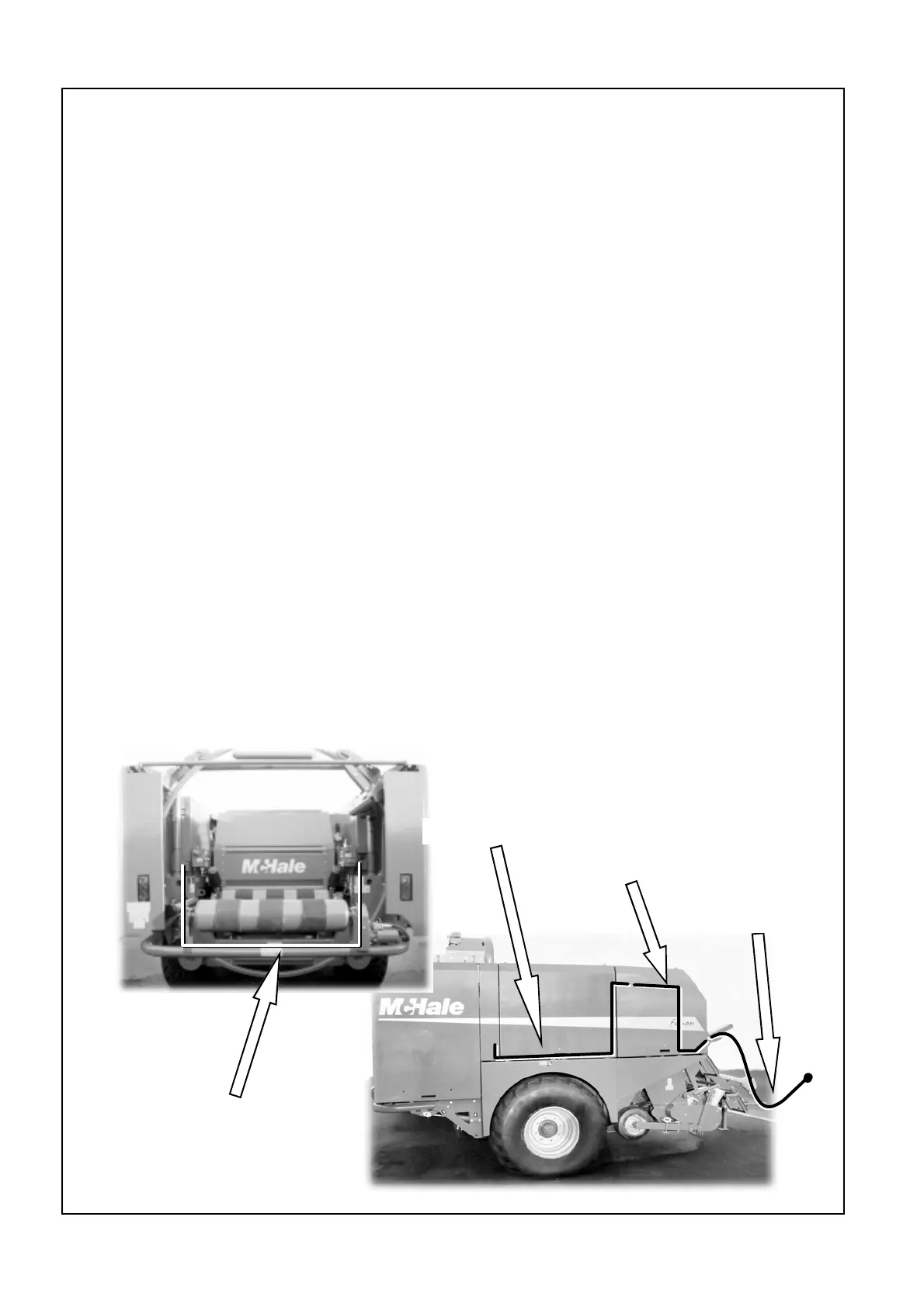
11.5.2: Wiring loom sections
11.5: Wiring diagrams
11.5.1: Safety warnings
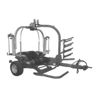
The wiring loom consists of a number of sections to make replacement easier.
The extension loom, the one most likely to get damaged, from the tractor to the
machine is joined underneath the platform. The connector is wrapped in
’self-amalgamating tape’ which should be carefully uncut and replaced.
Main loom
Valve to rear loom
Extension loom
Transverse loom
Before doing any maintenance work or troubleshooting on the Fusion 2 machine
Make sure the machine can not move by using wheel chocks and applying the
handbrake.
Remove PTO shaft if it is not totally necessary for testing, all control circuit
testing can be completed without the PTO running.
If the test does not require hydraulic oil flow disconnect hydraulic hoses from the
tractor.
Before any inspection is carried out from the open bale chamber the chamber
door lock must be turned to the locked position, see section 9.10
Never disable or defeat any safety circuit.
After any work on the machine the safety circuits must be checked to ensure they
are functioning correctly.
Please read the section 4 on General safety and section 5 on Specific safety
warnings.