McHale Fusion 2 electronic control system section
11- 17
McHale Fusion 2 round baler wrapper technical service manual
Issue 1: 0208
11.5.3: Guide to wiring diagrams
The wiring diagrams show the connections from the 37 pin AMP circular
connector to the machine mounted components.
Two ground circuits are used, one for the output circuits and the other for the
inputs. The ground circuit is only connected to machine metal at the net feed
clutch ground connection.
The forward and reverse rotate circuits are detailed on separate drawings to
make their operation and safety features clear.
Great care must be taken when fault finding the hardwired safety switches on the
dispenser access door and rear tip roller.
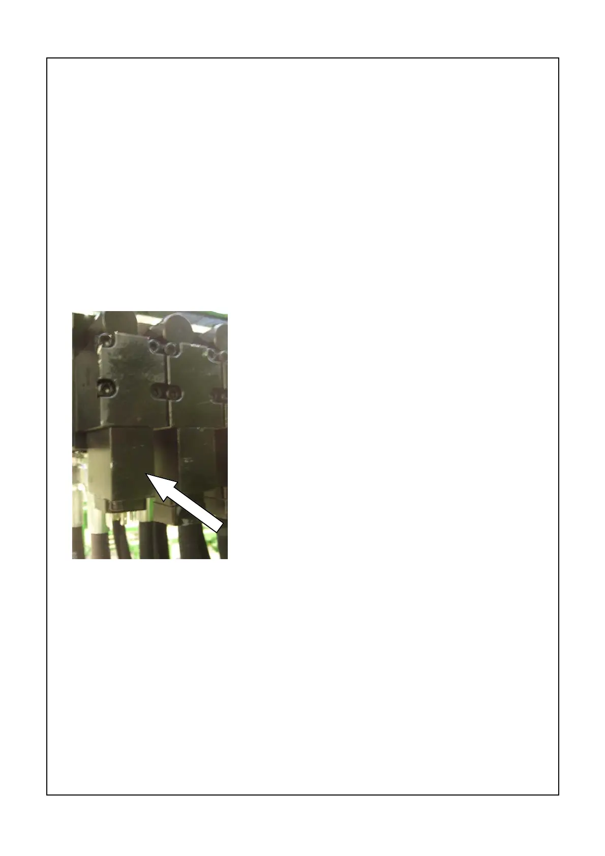
11.5.4: Main hydraulic valve solenoids
The main hydraulic valve is controlled by dual
proportional solenoids but only the slow forward
rotate circuit is operated in proportional mode. The
forward high speed oil flow and all other main valve
functions are limited by the adjusting screws on the
valve.
Solenoid connections
Terminal 1 = common ground
Terminal 2 = ‘B’ solenoid
Terminal 3 = ‘A’ solenoid