JET DRIVE
Page 6B-18 90-826883R2 JUNE 1998
INSTALLATION
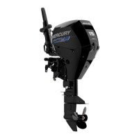
1. Grease the drive shaft, shear key, and impeller bore. Place the plastic sleeve (a) in-
side the impeller (b) and install impeller,shear key(c), shims (d)nut retainer (e),and
impellernut(f).Turnthe nuttightontheshafttoremoveanyplaybetweentheimpeller
and shaft. If the tabs on the retainer do not line up with the flats on the nut, remove
the nut and turn the retainer over and re-tighten the nut again.
a
b
f
c
d
e
a - Plastic Sleeve
b - Impeller
c - Shear Key
d - Shims
e - Nut Retainer
f - Impeller Nut
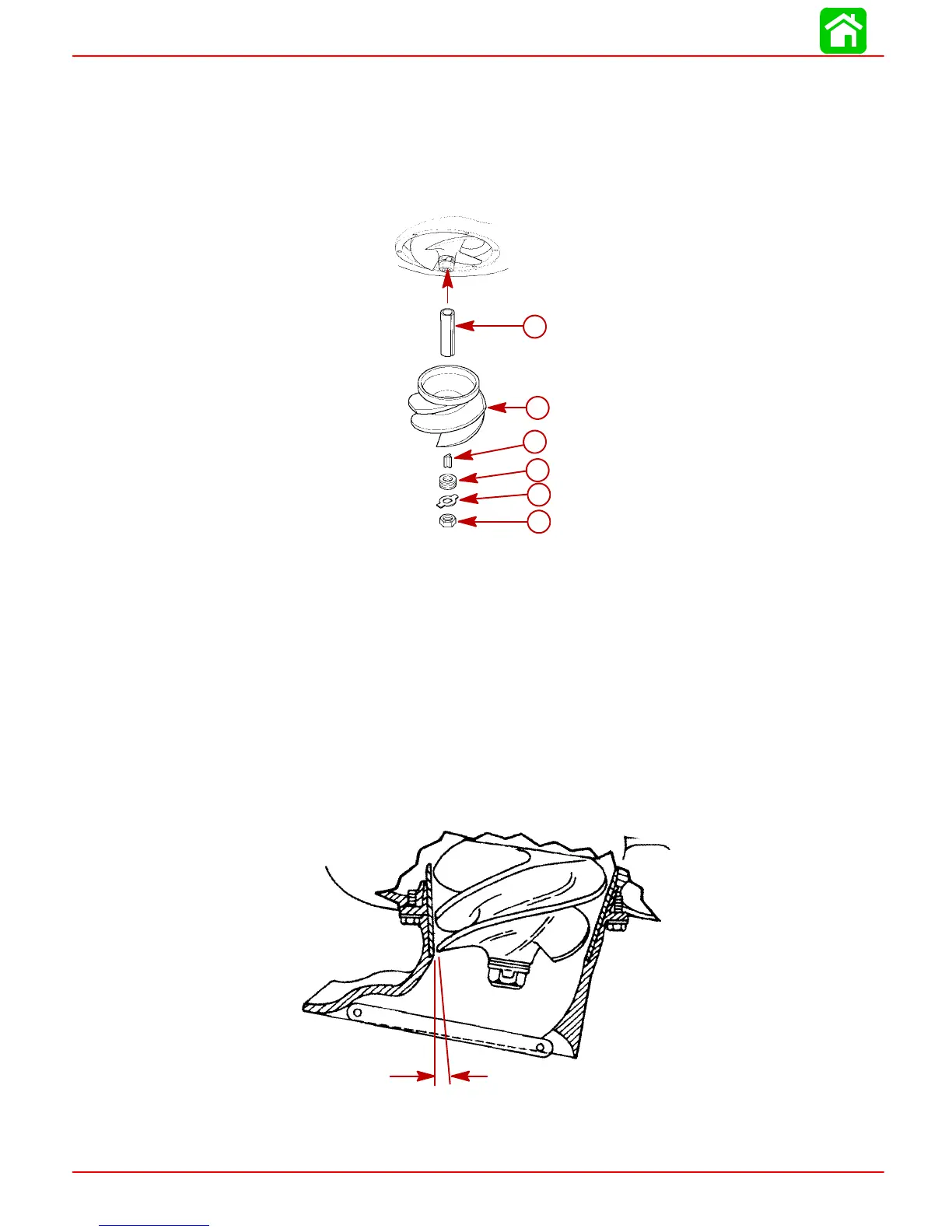
2. Temporarilyreinstallthewaterintakehousinginordertocheckforimpellerclearance.
The clearance between the impeller and liner should be 0.030 in. (0.8 mm). Shim
washers can be transferredto either side of theimpeller toraise orlower theimpeller
to the correct clearance setting. The water intake housing can be shifted side ways
a small amount in order to center the liner.
.03 in. (.8mm)
 Loading...