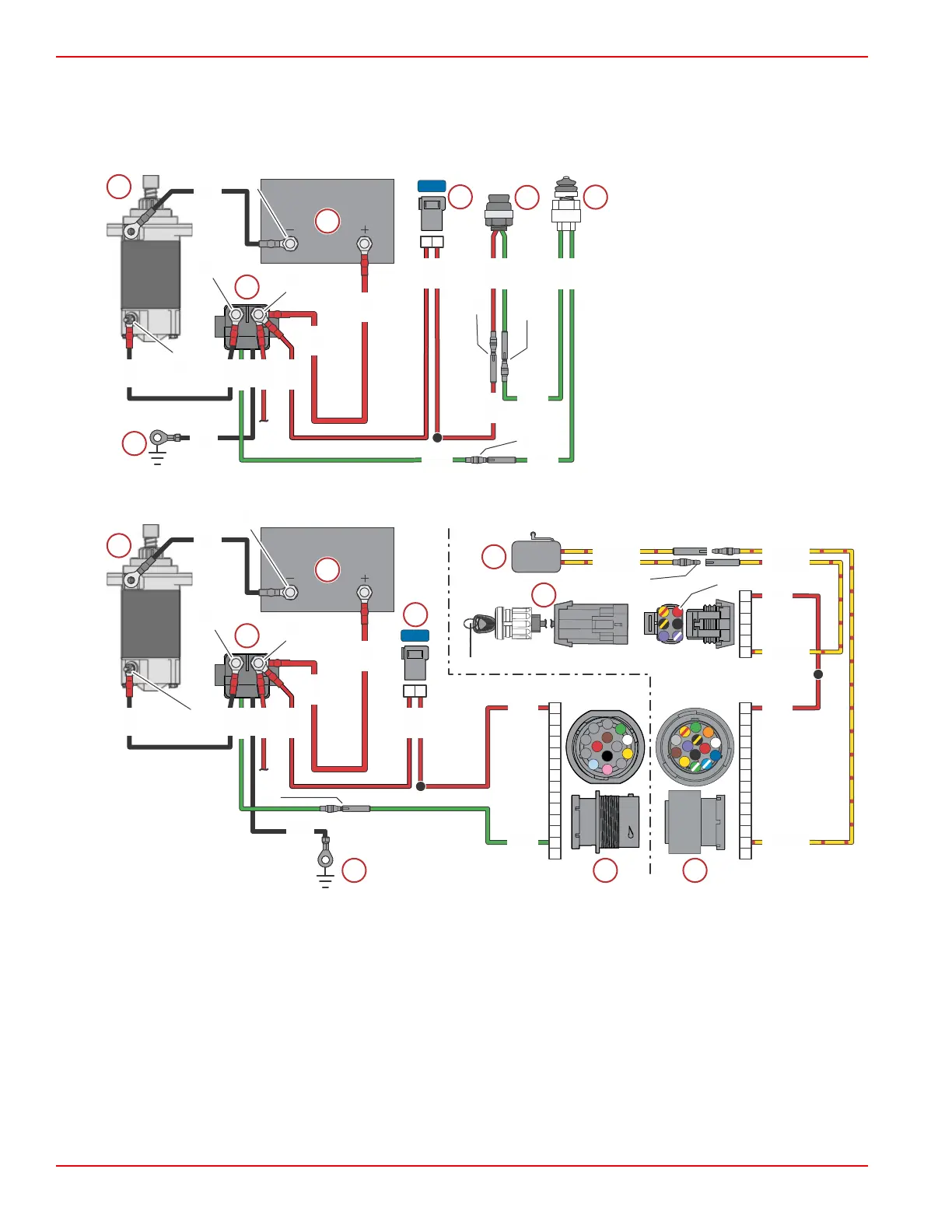
Starting System Wiring Diagrams
Use these wiring diagrams in conjunction with the Starting System T
roubleshooting Chart, following. The numbers indicate
test points identified in the troubleshooting chart.
Tiller Handle Models
a - Starter motor
b - Starter solenoid (disconnect at
TP2 for tests 2 through 6)
c - Battery
d - 15‑amp fuse
e - Cowl‑mounted start button
f - Neutral safety switch
g - Chassis ground
Remote Control Models
Typical
a - Starter motor
b - Starter solenoid (disconnect at TP2 for tests 2 through 6)
c - Battery
d - 15‑amp fuse
e - Chassis ground
f - Engine harness 14‑pin connector
g - Remote control harness 14‑pin connector
h - Key switch
i - Neutral start switch
GRN
BLK
RED
RED
RED
RED
RED
RED
RED
GRN
BLK
BLK
BLK
BLK
GRN
GRN
GRN
GRN
RED
GRN
63539
a
b
c
d
e
f
g
6
2
7
3
4
5
1
A
B
D
J
K
M
N
P
E
F
H
C
G
L
A
B
D
E
F
C
RED
YEL/RED
RED
YEL/RED
YEL/RED
YEL/RED
YEL/RED
YEL/RED
J5
E
H
J
K
L
M
N
A
B
C
D
F
G
P
15A
A
B
D
J
K
M
N
P
E
F
H
C
G
L
BLK
RED
RED
RED
RED
RED
RED
RED
GRN
BLK
BLK
BLK
BLK
GRN
63540
a
b
c
d
e
f
g
h
i
6
2
7
3
4
5
1
Charging and Starting Systems
Page 2B-12 © 2018 Mercury Marine 90-8M0125265 eng NOVEMBER 2017
 Loading...


