Idle Exhaust Port Cover
Removal and Inspection
1.
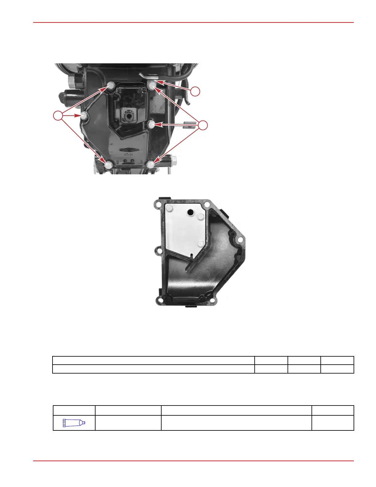
Remove the six screws securing the idle exhaust port cover, and remove the cover.
a - Vent tank vent hose fitting
b - Screws (6)
2. Remove the gasket.
3.
Remove the three screws securing the idle exhaust port plate.
4. Inspect and clean the idle exhaust port cover.
Installation
NOTE: Refer to the illustrations in the
Removal and Inspection
procedure, as required.
1. Install the idle exhaust port plate, and tighten the screws to the specified torque.
Description Nm lb‑in. lb‑ft
Idle exhaust port plate screw 4.0 35.4 –
2. Clean the mounting surfaces on the driveshaft housing and on the idle exhaust port cover.
3.
Place a new gasket onto the idle exhaust port cover.
4. Apply Loctite® 242 Threadlocker to the six idle exhaust port cover screws.
Tube Ref No. Description Where Used Part No.
66
Loctite® 242
Threadlocker
Idle exhaust port cover screws 92-809821
5. Attach the idle exhaust port cover and new gasket to the driveshaft housing, using the six screws. Ensure that the fitting for
the vent tank vent hose is threaded onto screw 4 (upper left corner), and that the hose is connected to the fitting.
6. Follow the sequence marked on the cover, and tighten the screws to the specified torque.
Clamp/Swivel Bracket and Driveshaft Housing
90-8M0125265 eng NOVEMBER 2017 © 2018 Mercury Marine Page 5A-19
 Loading...


