11. Attach the shift link to the shift lever using a retaining clip and washer.
12.
Install the throttle and shift bracket. Tighten the three screws to the specified torque.
Description Nm lb‑in. lb‑ft
Throttle and shift bracket screws 6.0 53.1 –
13. Attach the end of the neutral interlock cable to the shift lever. Temporarily secure the cable to the starter mounting bracket
with the two jam nuts.
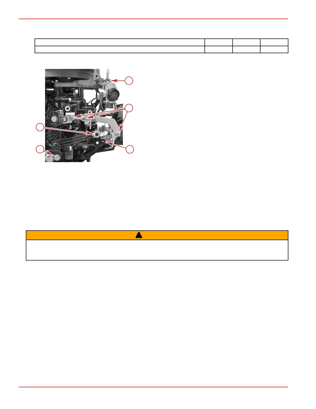
Bracket style may vary
a - Jam nuts
b - Interlock cable connection to the shift lever
c - Throttle and shift bracket screws (3)
d - Retaining clip and washer
e - Screw, two washers, and bushing
14.
Install the recoil starter assembly. Refer to Section 8A ‑ Recoil Starter. Adjust the interlock cable as required, and tighten
the jam nuts.
15.
Install the air box. Refer to Section 3C ‑ Air Box Installation.
16.
Install the tiller handle shift and throttle control cables. Refer to Section 7B ‑ Shift Cable Installation and Section 7B ‑
Throttle Cable Installation.
17.
Install the starboard driveshaft housing cover. Refer to Section 5A ‑ Driveshaft Housing Covers.
Remote Models
Throttle and Shift Linkage Removal
!
WARNING
Performing service or maintenance without first disconnecting the battery can cause product damage, personal injury, or
death
due to fire, explosion, electrical shock, or unexpected engine starting. Always disconnect the battery cables from the
battery before maintaining, servicing, installing, or removing engine or drive components.
1. Disconnect the battery cables from the battery.
2.
Remove the starboard driveshaft housing cover. Refer to Section 5A ‑ Driveshaft Housing Covers.
3.
Remove the air box and recoil starter.
• It is easiest to remove and install these two items together.
•
Refer to Section 3C ‑ Air Box Removal and Section 8A ‑ Recoil Starter.
Throttle and Shift Linkage
Page 7A-10 © 2018 Mercury Marine 90-8M0125265 eng NOVEMBER 2017
 Loading...


