ECM Systems Control Matrix
ECM Control Item Description
Ignition timing Controls the optimum ignition timing according to the current operating conditions
Fuel injection
Controls the fuel injection pulse width (duration) for optimum efficiency according to current
operating condition
Idle air control (IAC)
Stabilizes the engine RPM when idling and during quick engine RPM deceleration by managing
the duty cycle driving the IAC in order to control bypass air entering the intake manifold
Tachometer Sends out six tachometer pulses per engine revolution (12 pole)
Warning horn and light
Refer to Section 1E ‑ W
arning System Operation
Fault and running data
memory
• Engine running time
• Over temperature and time of occurrence
• Engine Guardian (overspeed, and speed reduction to 2800 RPM or less)
• Sensor failures
Troubleshooting
The ECM is a highly reliable component, and is rarely the source of a running issue. However, if the ECM should completely
fail, the engine will not operate.
For troubleshooting, refer to:
•
Section 1E ‑ Accessing ECM Information with CDS G3
•
The appropriate engine wiring diagram in Section 9A ‑ Color Diagrams
Removal
1.
For models with electric start, disconnect the battery, and remove the positive battery cable from the starter solenoid.
2. For models with power tilt, remove the positive and negative wires from the tilt up relay.
3. Remove the 15‑amp fuse block from its holder on the front of the ECM rubber mount.
4. Slide the ECM and rubber mount off of the ECM bracket.
5. Disconnect the ECM from the engine harness.
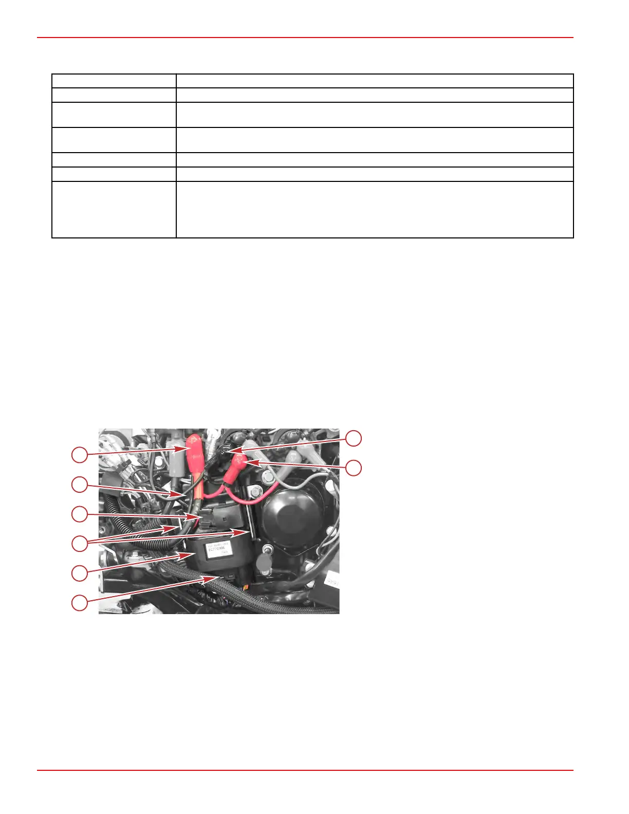
Power tilt model shown, others similar
a - Engine harness connector
b - Rubber mount
c - ECM bracket
d - 15‑amp fuse block
e - ECM
f - Positive battery cable (models with electric
start only)
g - Negative wire connection at the tilt up relay
(models with power tilt only)
h - Positive wire connection at the tilt up relay
(models with power tilt only)
6. Remove the ECM from its rubber mount.
Installation
1. Slide the ECM rubber mount over the ECM.
2. Connect the ECM to the engine harness.
3. Slide the ECM and mount onto the ECM bracket. Ensure that the metal bracket protrudes through the rubber mount on
either side.
4. Insert the 15‑amp fuse block into its holder on the front of the ECM rubber mount.
5. For models with power tilt, connect the positive and negative wires to the tilt up relay.
6. For models with electric start, connect the positive battery cable to the starter solenoid.
Ignition
Page 2A-4 © 2018 Mercury Marine 90-8M0125265 eng NOVEMBER 2017
 Loading...


