b. Cut the cable tie that secures the power tilt wires to the electrical bracket.
c.
Pull the power tilt pump wires through the grommet in the port cover.
d. If the engine has a cowl‑mounted tilt switch, disconnect the switch from the engine harness.
6. Loosen the three captive screws that secure the port cover, and remove the cover.
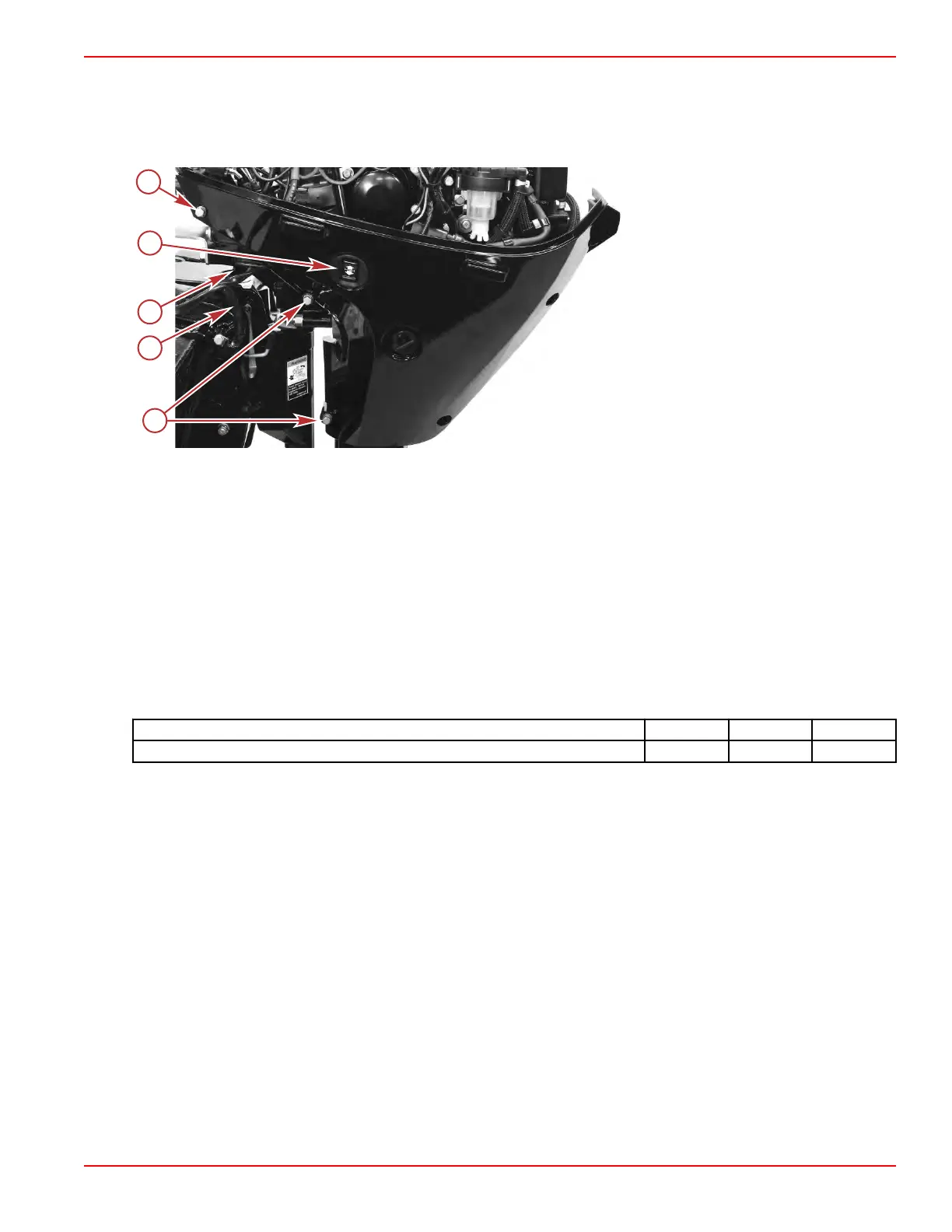
a - Screws (3)
b - Power tilt pump wires
c - Grommet for power tilt pump wires
d - Cowl‑mounted tilt switch (optional for
power tilt models only)
Installation
NOTE: Refer to
Removal
, preceding, for illustrations as required.
1. For models with power tilt:
a. Route the power tilt pump wires through the port cover. Ensure that the grommet remains properly seated in the
cover.
b. Connect the green tilt wire to the down relay terminal, and connect the blue tilt wire to the up relay terminal. Cover the
connections with the attached rubber boots, and secure the wires to the electrical bracket with a cable tie.
c. If the engine has a cowl‑mounted tilt switch, ensure that the tilt switch is correctly installed in the port cover, and
connect the switch to the engine harness.
2. Position the port cover on the driveshaft housing and secure it with the three captive screws.
3. Position the starboard cover on the driveshaft housing and secure it with the seven captive screws.
4. Tighten the three port‑side screws, the seven starboard‑side screws, and the cowl latch screw to the specified torque.
Description Nm lb‑in. lb‑ft
Driveshaft housing cover and cowl latch screws (11) 6.0 53.1 –
5. Attach the cowl seal.
6.
Position the top cowl and secure it with the cowl latch.
Front Cowl
The front cowl houses the fuel connection, the diagnostic light, and the optional start push‑button. It also has a catch for the top
cowl.
Removal
1.
Remove the driveshaft housing covers. Refer to Driveshaft Housing Covers.
Clamp/Swivel Bracket and Driveshaft Housing
90-8M0125265 eng NOVEMBER 2017 © 2018 Mercury Marine Page 5A-17
 Loading...


