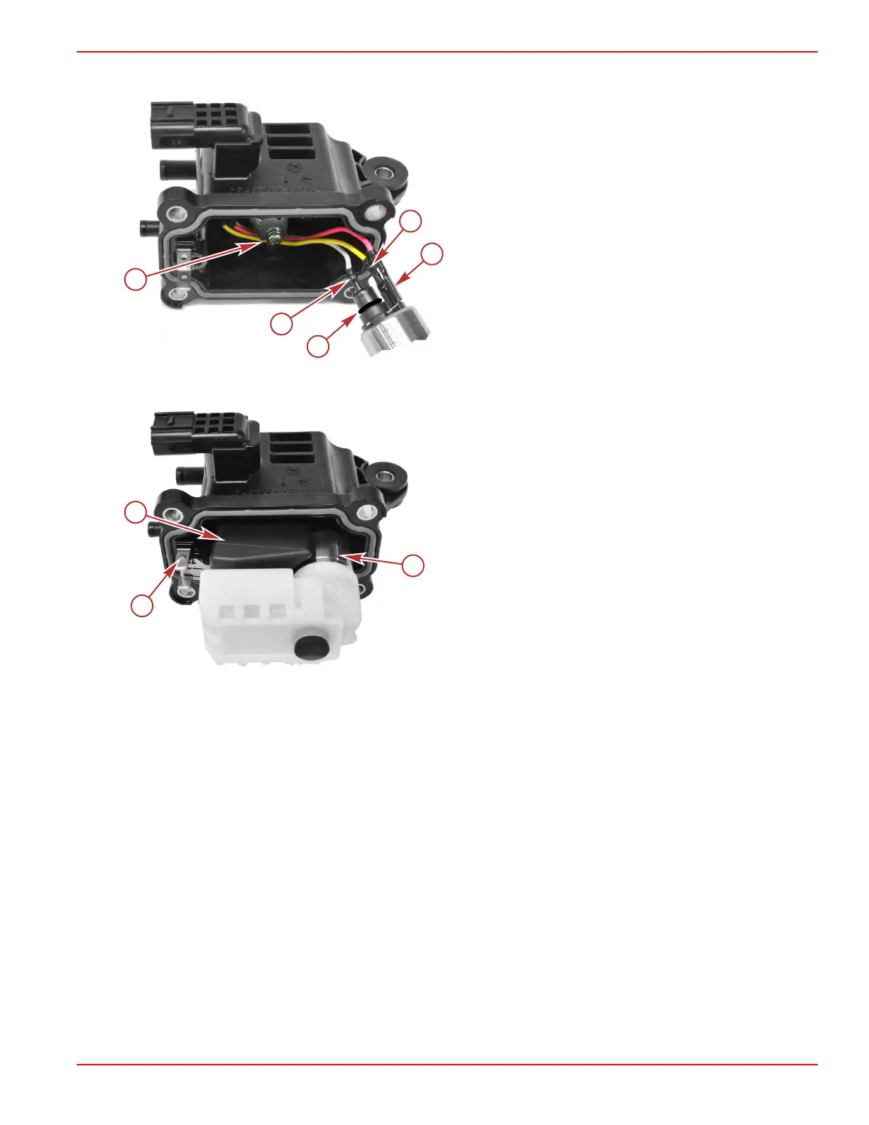
NOTE: When viewing the fuel pump electrical terminals from the top, the clockwise order of connection is white, yellow,
and red.
a - Wires routed outside of screw boss
b - White wire spade terminal
c - Yellow wire spade terminal
d - Red wire spade terminal
e - O‑ring
7. Insert the fuel inlet needle into the VST cover, place the float in position, and secure it with the float pin.
8.
Ensure that the O‑ring is in position on the fuel pump, and press it into position in the VST cover.
a - High‑pressure fuel pump
b - Float pin
c - Float
9. Assemble the two halves of the VST assembly, and secure with four screws.
Fuel Cooler
To remove the cover on the VST's fuel cooler chamber:
1.
Remove four screws and remove the fuel cooler cover.
Service Procedures
90-8M0125265 eng NOVEMBER 2017 © 2018 Mercury Marine Page 3C-15
 Loading...


