Description Nm lb‑in. lb‑ft
Idle exhaust port cover screws 6.0 53.1 –
Powerhead/Midsection Assembly Separation
Several procedures require the separation of the powerhead/midsection assembly from the clamp/swivel bracket assembly.
Refer to the following procedures as required.
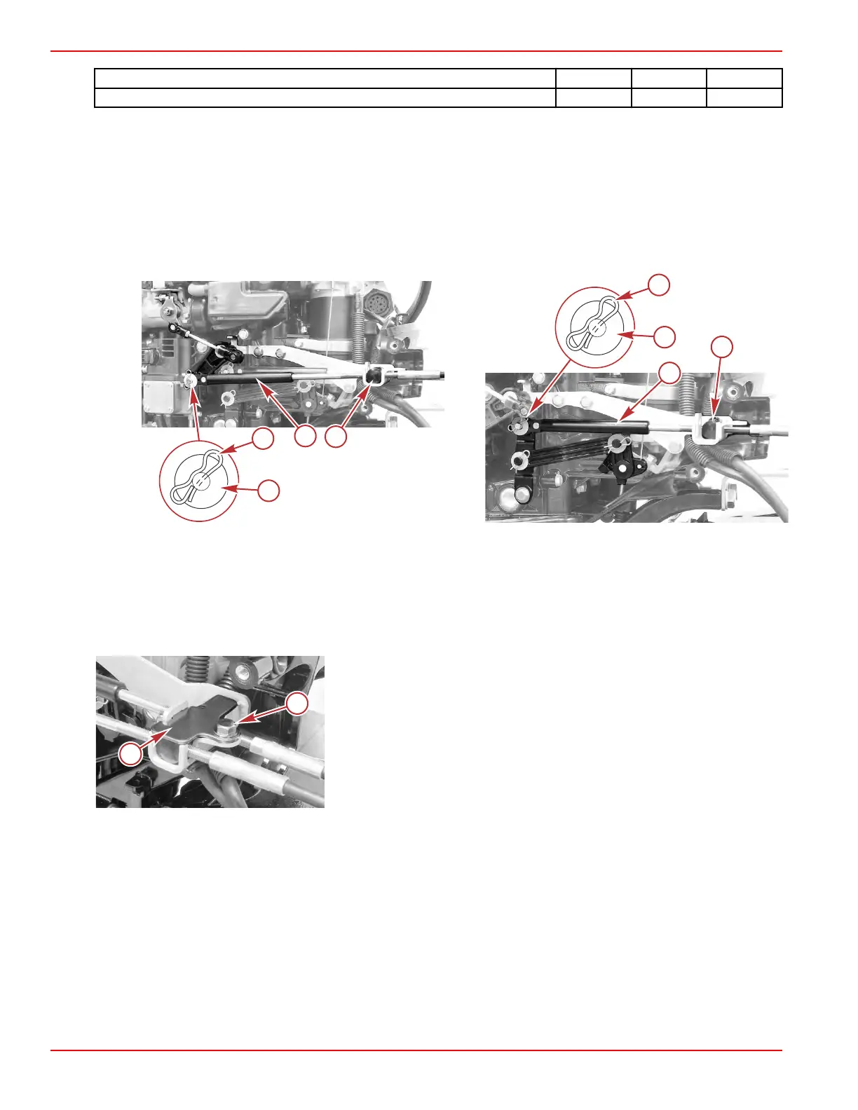
Remote Control Throttle and Shift Cables
The throttle and shift cables must be removed before the powerhead/midsection assembly can be separated from the clamp/
swivel bracket assembly.
1.
Remove the bow‑tie retainers and washers from the throttle and shift cables.
a - Bow‑tie retainer
b - Flat washer
c - Throttle cable
d - Cable barrel
a - Bow‑tie retainer
b - Flat washer
c - Shift cable
d - Cable barrel
2. Remove the screw from the cable barrel retainer, and remove the throttle and shift cables.
a - Cable barrel retainer
b - Screw
Removal
1.
For tiller handle models, remove the tiller handle. Refer to Section 7B ‑ T
iller Handle Removal.
2.
Completely remove both driveshaft housing covers. Refer to Driveshaft Housing Covers.
3.
For electric start models, remove the starter motor. Refer to Section 2B ‑ Starter Motor Removal.
4. Remove the upper shift shaft:
Clamp/Swivel Bracket and Driveshaft Housing
Page 5A-20 © 2018 Mercury Marine 90-8M0125265 eng NOVEMBER 2017
 Loading...


