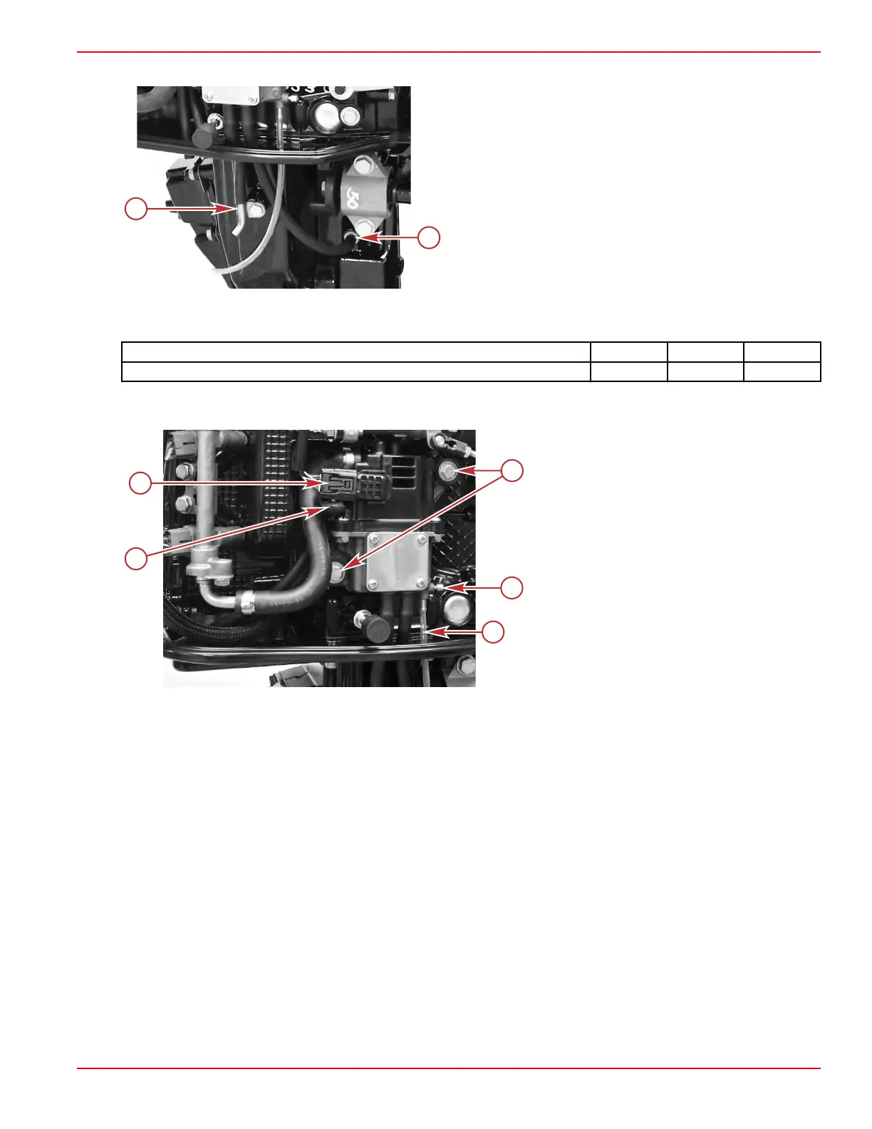
4. Connect the fuel cooler water supply and water pump indicator hoses to the fittings located in the driveshaft housing.
a - Water pump indicator hose fitting
b - Fuel cooler water supply hose fitting
5. Attach the low‑pressure fuel supply hose to the VST assembly, and secure it with a hose clamp.
6.
Attach the VST assembly to the cylinder block with two screws. Tighten the screws to the specified torque.
Description Nm lb‑in. lb‑ft
VST mounting screws 6.0 53.1 –
7. Connect the high‑pressure fuel pump electrical connector to the engine harness.
8.
Ensure that the VST drain hose is routed through the midplate, and attach the hose to the drain fitting.
a - Hose clamp securing the low‑pressure fuel
supply hose
b - High‑pressure fuel pump electrical
connector
c - Screws (2)
d - VST drain screw
e - VST drain hose
9.
Install the starboard driveshaft housing cover. Refer to Section 5A ‑ Driveshaft Housing Covers.
Camshaft Gear Cover/Vent Tank
The camshaft gear cover assembly incorporates a secondary vent tank for the vapor separator tank (VST).
NOTE: The following procedures assume that the air box and recoil starter assembly have been removed. For details on those
procedures, refer to
Air Box
and
Section 8A
‑
Recoil Starter
.
Removal
1. Remove the vent hose from the cover assembly.
2. Remove the two vapor separator (VST) tank hoses from the cover assembly.
3. Remove the crankcase breather hose.
Service Procedures
90-8M0125265 eng NOVEMBER 2017 © 2018 Mercury Marine Page 3C-17
 Loading...


