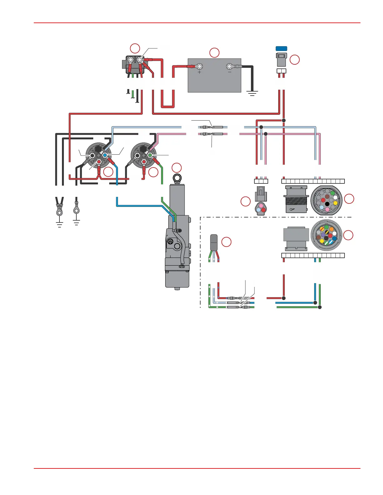
Power Tilt Electrical Circuit - Remote Control
Typical (side mount remote control shown, others similar)
a - Starter solenoid
b - Battery
c - 15‑amp fuse
d - Tilt up relay
e - Tilt down relay
f - Power tilt assembly
g - Cowl‑mounted tilt switch
h - Engine harness 14‑pin connector
i - Side mount remote control harness 14‑pin connector
j - Tilt switch on side mount remote control
Tilt System Troubleshooting Charts
Troubleshooting the Down Circuit
NOTE: Refer to the preceding wiring diagrams for test points when troubleshooting the electrical systems. Test points are
specified by number.
A B D
J
K M N PE F HC G L
UP
DN
RED
BLU/WHT
GRN/WHT
RED/PPL
LT BLU/WHT
GRN/WHT
RED
BLU/WHT
GRN/WHT
J5
J8
J7
A B D
J
K M N PE F HC G L
E
H
J
K
L
M
N
A
B
C
D
F
G
P
15A
BLK
BLK
BLK
BLK
BLK
BLK
RED
RED
RED
RED
RED
GRN
BLK
BLK
RED
RED
RED
RED
LT BLU LT BLU
PNK PNK
LT BLU
PNK
RED
GRN
BLU
LT BLU
PNK
63523
a
b
c
d
e
f
g
h
i
j
3, 9
2
6
10
5
1
8
4
7
Power Tilt
90-8M0125265 eng NOVEMBER 2017 © 2018 Mercury Marine Page 5B-15
 Loading...


