Valve Adjustments
IMPORTANT: The timing belt and gears must be installed in the correct position or valve damage may occur.
1.
Remove the following components:
• Air box and recoil starter
• It is easiest to remove and install these two items together.
•
Refer to Section 3C ‑ Air Box Removal and Section 8A ‑ Recoil Starter.
•
Camshaft gear cover/vent tank. Refer to Section 3C ‑ Camshaft Gear Cover/Vent Tank.
•
Disconnect the inlet and outlet fuel pump hoses. Refer to Section 4A ‑ Powerhead Removal.
•
Cylinder head cover. Refer to Cylinder Head Removal.
• Spark plugs.
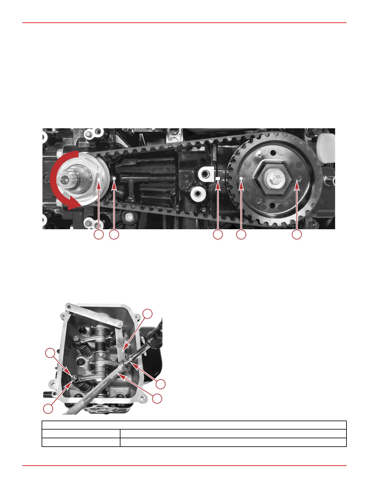
2. Rotate the crankshaft until the timing marks on the crankshaft and camshaft are in proper alignment.
a - Crankshaft drive gear timing mark
b - Timing mark on the cylinder block for the crankshaft
c - Timing mark on the cylinder block for the camshaft
d - Timing mark for #1 cylinder
e - Timing mark for #2 cylinder
3. Measure valve clearance with a feeler gauge. Adjust if out of specification.
a - Feeler gauge
b - Square drive socket
c - Wrench
d - Locknut
e - Adjusting screw
Valve Clearance (Cold)
Intake 0.13–0.17 mm (0.005–0.007 in.)
Exhaust 0.18–0.22 mm (0.007–0.008 in.)
4. Perform the following adjustment steps if out of specification:
Cylinder Head
Page 4B-10 © 2018 Mercury Marine 90-8M0125265 eng NOVEMBER 2017
 Loading...


