14. Tighten the bolts to the specified torque in sequence in two steps.
1
2
3
4
5
6
7
8
9
10
64052
1
2
3
4
5
6
7
8
9
10
Description Nm lb‑in. lb‑ft
Main bearing bolts (1–4) (M8 x 50)
First
10.0 88.5 –
Final
23.5 – 17.3
Crankcase cover bolts (5–10) (M6 x 30)
First
6.0 53.1 –
Final
11.5 101.8 –
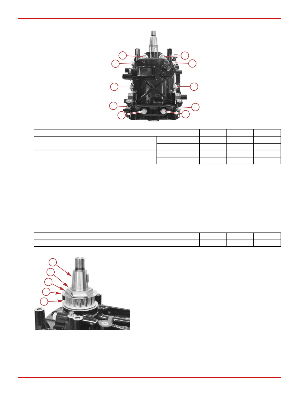
Crankshaft Timing Gear Installation
1.
Install the timing gear key into the crankshaft.
2. Install the timing gear.
3. Install the belt guide with the dot side up.
IMPORTANT: The belt guide outside edge is curved. Ensure the belt guide outside curved edge faces up toward the
flywheel.
4. Install the lockwasher with the bent tang inserted into the keyway on the timing gear.
5. Install the timing gear nut.
6. Install the flywheel key. Tighten the timing gear nut to the specified torque.
Description Nm lb‑in. lb‑ft
Timing gear nut 64.0 – 47.2
7. Bend the lockwasher against one flat on the nut.
a - Crankshaft
b - Nut
c - Lockwasher
d - Belt guide
e - Timing gear
Thermostat, Exhaust Cover, and Anode Installation
1.
Install the cylinder head. Refer to Section 4B ‑ Cylinder Head Installation.
NOTE: Install the spark plugs as directed, but do not install the throttle body or removed electrical components at this time.
2. Install a new exhaust cover gasket.
3. Install the exhaust cover, and start but do not tighten the five M6 x 25 screws.
Cylinder Block/Crankcase
Page 4A-28 © 2018 Mercury Marine 90-8M0125265 eng NOVEMBER 2017
 Loading...


