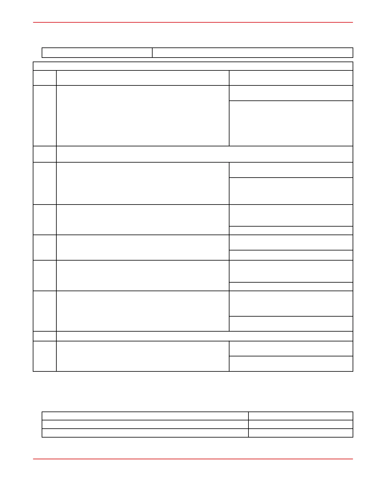
Starting System Troubleshooting Chart
Location of test points (TP) called out in the chart are numbered in the preceding diagrams.
DMT 2004 Digital Multimeter 91‑892647A01
Starter Does Not Work
Test
Number
Procedure Reading: Action
Test 1
Test the ground connection:
Connect the leads of an ohmmeter (R x 1 scale) between the
negative (–) battery post (TP1) and a common powerhead ground.
Continuity: The ground connection is good.
Proceed to Test 2.
No continuity: There is an open circuit in the
negative (–) battery cable between the negative
(–) battery post and the starter motor.
•
Check the cable for loose or corroded
connections.
• Test the cable for continuity.
–
IMPORTANT: Disconnect the positive starter motor cable from the starter solenoid at test point 2 (TP2) before
performing tests 2 through 6, to prevent unexpected engine cranking.
Test 2
Identify the circuit with the trouble:
1. Ensure that the shift lever is in neutral.
2. Change the meter to read DC voltage.
3. Connect the voltmeter between engine ground and TP2.
4. Turn the ignition key to "START" or push in the start button.
Battery voltage:
The trouble is in the starter
motor circuit. Proceed to Test 7.
No voltage: The trouble is in the control circuit.
Proceed to Test 3.
Test 3
Test the starter solenoid:
1. Connect a voltmeter between engine ground and TP3.
2. Turn the ignition key to "START" or push in the start button.
Battery voltage: Check the starter solenoid coil
wiring. If it is okay, then the starter solenoid is
defective.
No voltage: Proceed to Test 4.
Test 4
Test the neutral start switch:
1.
Connect a voltmeter between engine ground and TP4.
2. Turn the ignition key to "START" or push in the start button.
Battery voltage: Neutral start switch is open, or
a wire is open between the switch and TP3.
No voltage: Proceed to Test 5.
Test 5
Test the ignition key or start button:
1.
Connect a voltmeter between engine ground and TP5.
2. Turn the ignition key to "START" or push in the start button.
Battery voltage: Defective ignition key or start
button, or a wire is open between the switch and
TP4.
No voltage: Proceed to Test 6.
Test 6
Test the circuit between TP5 and TP6:
1.
Connect a voltmeter between engine ground and TP6.
2. Turn the ignition key to "START" or push in the start button.
Battery voltage:
•
Check the 15‑amp fuse.
• Check for an open between TP5 and TP6.
No voltage: Check the positive (+) battery cable
between the battery and TP6.
–
IMPORTANT: Reconnect the positive starter motor cable to the starter solenoid at TP2 before performing Test 7.
Test 7
Test the starter motor circuit:
1.
Connect a voltmeter between engine ground and TP7.
2. Turn the ignition key to "START" or push in the start button.
Battery voltage: Check the starter for a
corroded ground. If OK, check the starter motor.
No voltage: Check the positive starter cable for
poor connection or open circuit.
Starter Motor
Starter Motor Current Draw
IMPORTANT: The starter motor current draw test must be performed with a fully charged battery.
Condition Current Draw
No load test 13 A
Normal operation (cranking) 45–50 A
Charging and Starting Systems
90-8M0125265 eng NOVEMBER 2017 © 2018 Mercury Marine Page 2B-13
 Loading...


