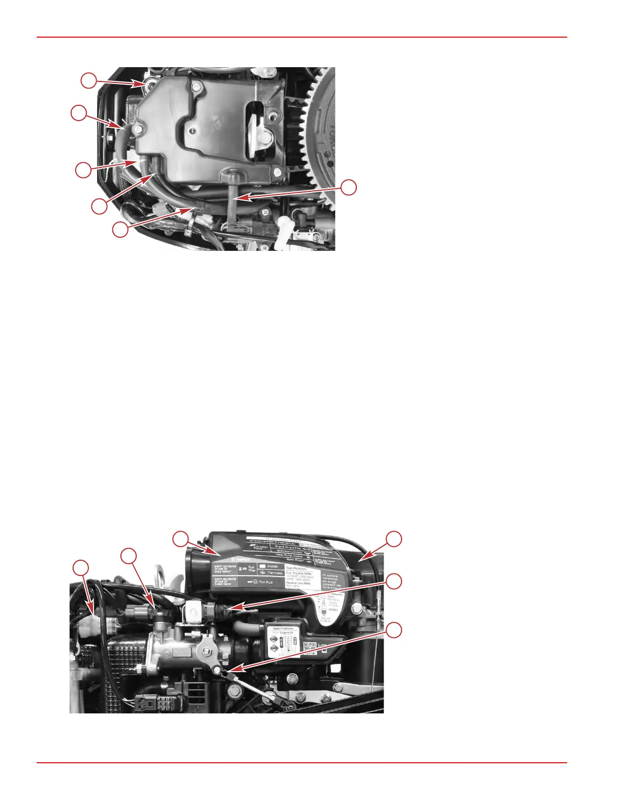
4. Lift the cover assembly to remove it from the two pins that secure it to the engine.
a - Pin (2)
b - Crankcase breather hose
c - VST hose with white mark
d - VST hose without white mark
e - Clip
f - Vent hose
Installation
1.
Position the cover assembly onto the engine. Ensure that the grommets do not become dislodged from the cover
assembly.
2. Route the crankcase breather hose across the tray and secure it to the valve cover with a spring clamp.
NOTE: It may be easier to connect the crankcase hose to the air box if you route the hose, but do not connect it. Be
certain, however, to complete the connection at the valve cover prior to placing the engine back into service.
3. Attach the two hoses from the vapor separator tank. The hose with the white mark attaches to the upper fitting.
4. Attach the vent hose.
Throttle Body
Throttle Body Removal
1. Remove the air box and recoil starter.
• It is easiest to remove and install these two items together.
•
Refer to Air Box Removal and Section 8A ‑ Recoil Starter.
2. Disconnect the idle air control (IAC) valve from the engine harness.
3. Remove the throttle link from the throttle cam.
4. Disconnect the throttle position sensor (TPS) from the engine harness.
5.
Remove the temperature and manifold absolute pressure (TMAP) sensor. Refer to Section 2A ‑ Temperature and
Manifold Absolute Pressure (TMAP) Sensor.
a - Air box
b - Recoil starter assembly
c - IAC valve harness connector
d - Throttle link
e - TPS harness connector
f - TMAP sensor
Service Procedures
Page 3C-18 © 2018 Mercury Marine 90-8M0125265 eng NOVEMBER 2017
 Loading...


