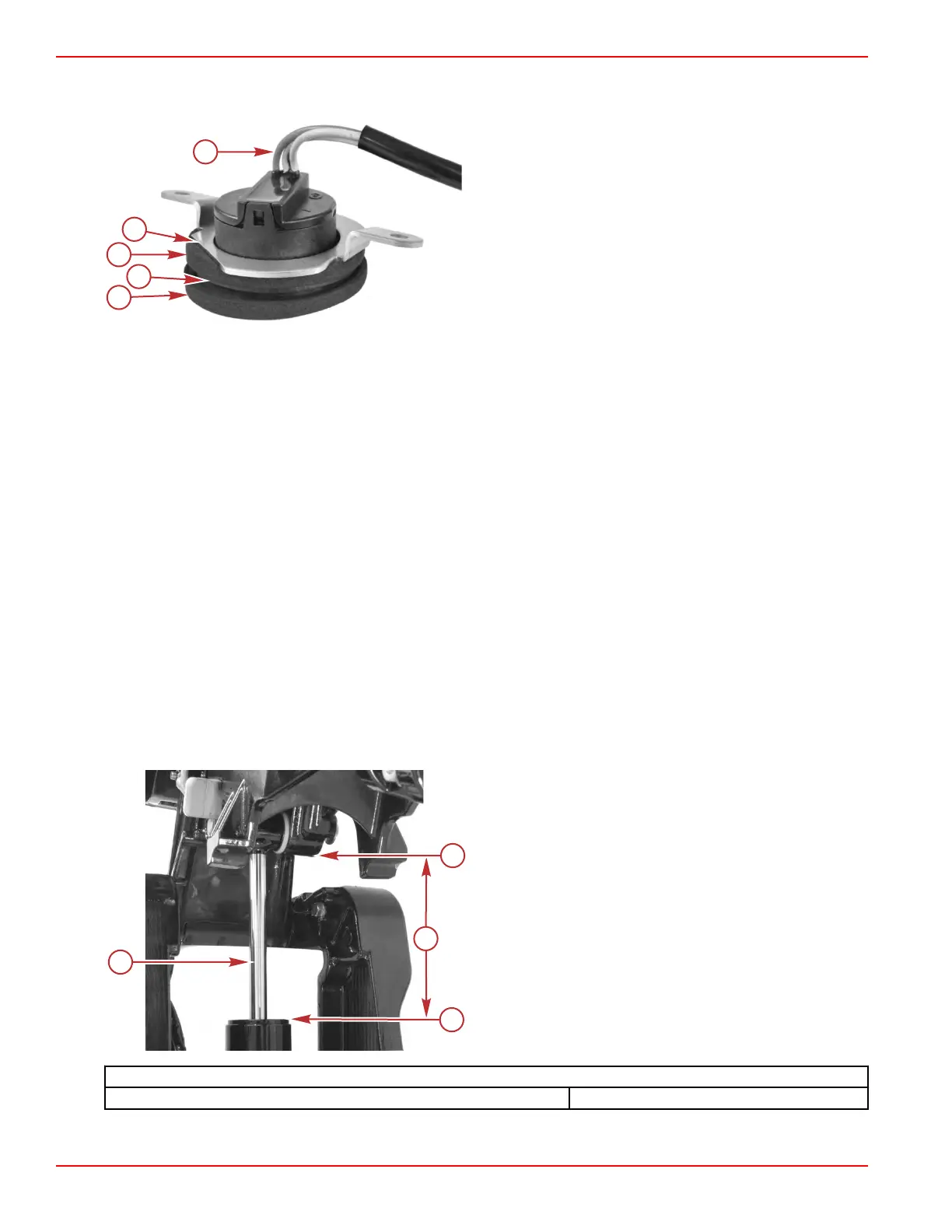
• The switch should be positioned with the harness at the bottom.
•
Ensure that the switch is vertical before tightening the screws.
a - Foam gasket
b - Flange on tilt switch housing
c - Flat edge of mounting bracket
d - Switch harness exits at the bottom of the switch
3.
Install the port‑side driveshaft housing cover. Refer to Section 5A ‑ Driveshaft Housing Covers.
4.
Confirm proper up/down operation of the tilt switch.
Troubleshooting the Power Tilt System
Preliminary Troubleshooting Steps
Determine if the problem is hydraulic or electrical related. Most often, if the electric motor operates, the problem is in the
hydraulic system. If the electric motor does not operate, the problem is in the electrical system.
IMPORTANT: Operate the power tilt system after each check to see if the problem is corrected. If the problem has not been
corrected, proceed with the next check.
1. Check that the manual release valve is tightened fully (clockwise).
2.
Check the power tilt pump fluid level in the full up position. Fill if necessary. Refer to Check Fluid and Purge the Power
Tilt System.
3. Check for external leakage in the power tilt system. Replace/repair the defective component if a leak is found. Maximum
acceptable power tilt cylinder leak‑down is 55 mm (2.2 in.) within a 24 hour period. Refer to Power Tilt Leakage Test
Procedure.
Power Tilt Leakage Test Procedure
Method 1
1. Extend the power tilt cylinder to the full up position.
2. Measure the distance between the cylinder cap and the bottom of the power tilt cylinder rod eye.
3. Wait 24 hours and measure the distance again.
a - Cylinder rod
b - Rod eye
c - Cylinder cap
d - Measured distance
Power Tilt System Leakage Specification
Cylinder rod leak‑down in 24 hour period Less than 55 mm (2.2 in.)
Power Tilt
Page 5B-10 © 2018 Mercury Marine 90-8M0125265 eng NOVEMBER 2017
 Loading...


