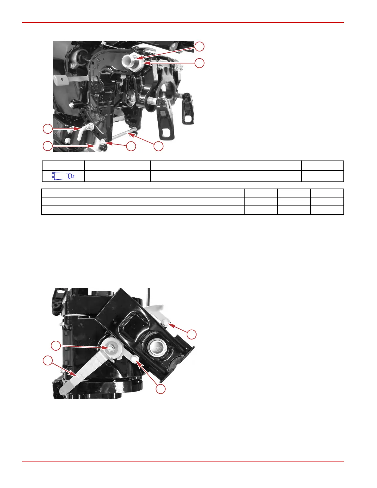
9. Install the tilt pin.
a - Tilt tube
b - Nut
c - Spacer
d - Nut and washer
e - Tilt pin
f - Anode
Tube Ref No. Description Where Used Part No.
95
2-4-C with PTFE Tilt tube washer 92-802859A 1
Description Nm lb‑in. lb‑ft
Tilt tube locknut 24.0 – 17.7
Spacer nut 6.0 53.1 –
Steering Arm Removal
1.
Separate the powerhead/driveshaft housing/gearcase assembly from the clamp bracket/swivel bracket/steering arm
assembly. Refer to Powerhead/Midsection Assembly Separation.
NOTE: The air box need not be fully removed for this procedure. Removing the three screws and moving the air box far
enough out of the way to allow the recoil starter to be removed is sufficient. This will ease reassembly.
NOTE: Remove the tiller handle, and temporarily secure it to the powerhead with a cable tie to prevent damage.
2. Remove one locknut to remove the copilot handle.
3. Remove two screws with washers to remove the remaining copilot components from the swivel bracket.
a - Copilot handle
b - Locknut
c - Screw with washer
Clamp/Swivel Bracket and Driveshaft Housing
Page 5A-40 © 2018 Mercury Marine 90-8M0125265 eng NOVEMBER 2017
 Loading...


