12. Electric start models: Connect the engine harness red bullet connector to the voltage regulator/rectifier.
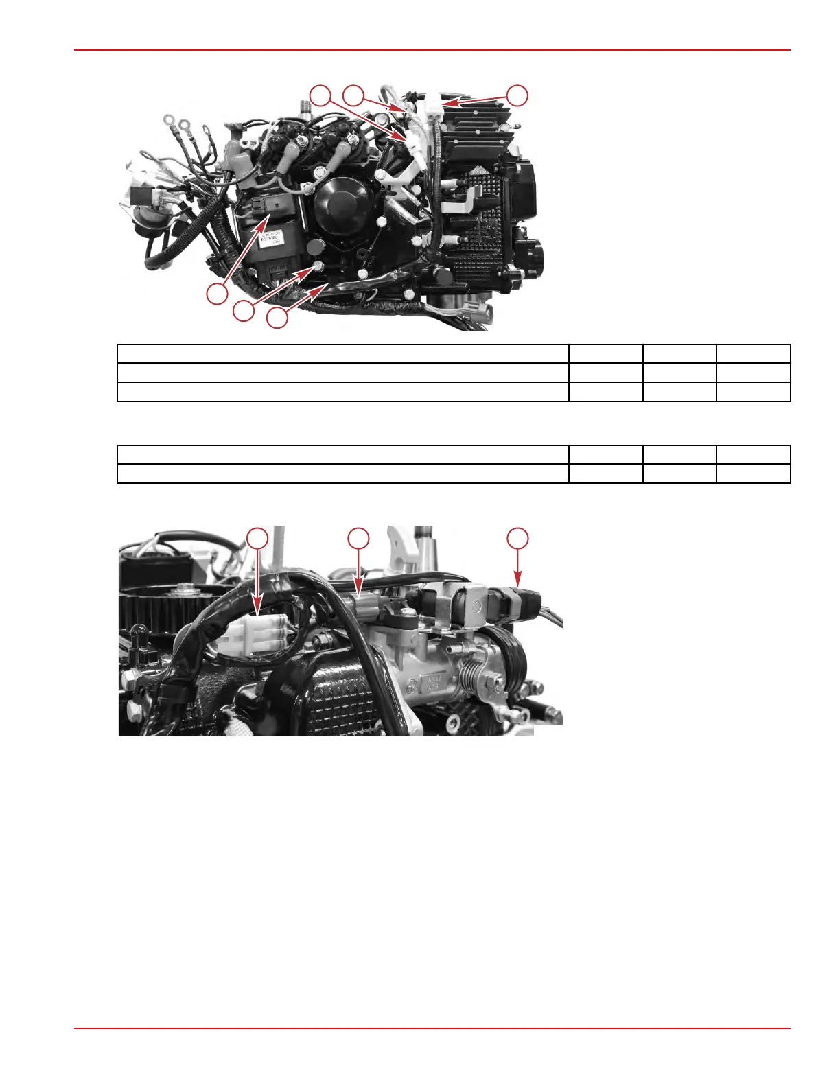
a - 2‑pin ECT sensor connector
b - Voltage regulator/rectifier red bullet
connector
c - Yellow fuse housing
d - Oil pressure switch with rubber boot
installed (behind harness)
e - Ground terminal
f - Black fuse housing
Description Nm lb‑in. lb‑ft
Ground terminal screw 6.0 53.1 –
Oil pressure switch screw 1.5 13.3 –
13.
Install the ignition coil. Refer to Section 2A ‑ Ignition Coil. Be certain to tighten the mounting screws to the specified
torque.
Description Nm lb‑in. lb‑ft
Ignition coil mounting screw (M6 x 25) (2) 6.0 53.1 –
14. Connect the throttle position sensor (TPS), temperature and manifold absolute pressure (TMAP) sensor, and the idle air
control (IAC) to the engine harness.
a - TPS connector
b - TMAP sensor connector
c - IAC connector
IMPORTANT: Additional connections will be made after the powerhead is installed onto the driveshaft housing. Secure all loose
items as necessary, for the powerhead installation.
Powerhead Installation
IMPORTANT: This procedure assumes that all components are in the state as removed in Powerhead Removal (for example,
the VST and fuel rail remain connected by the high‑pressure fuel hose). If any additional disassembly was performed, refer to
the appropriate service procedure for reassembly details.
This procedure contains steps for an electric start, power tilt model. Some steps will not apply to other models.
1.
Attach the powerhead to the driveshaft housing:
a. Ensure that the powerhead gasket, driveshaft seal, and rubber seal are in place on the driveshaft housing. Refer to
Section 5A ‑ Driveshaft Housing Installation for details.
b. Install the powerhead onto the driveshaft and driveshaft housing.
Cylinder Block/Crankcase
90-8M0125265 eng NOVEMBER 2017 © 2018 Mercury Marine Page 4A-33
 Loading...


