c. Install six screws to secure the powerhead to the driveshaft housing assembly. Tighten the screws to the specified
torque in two stages.
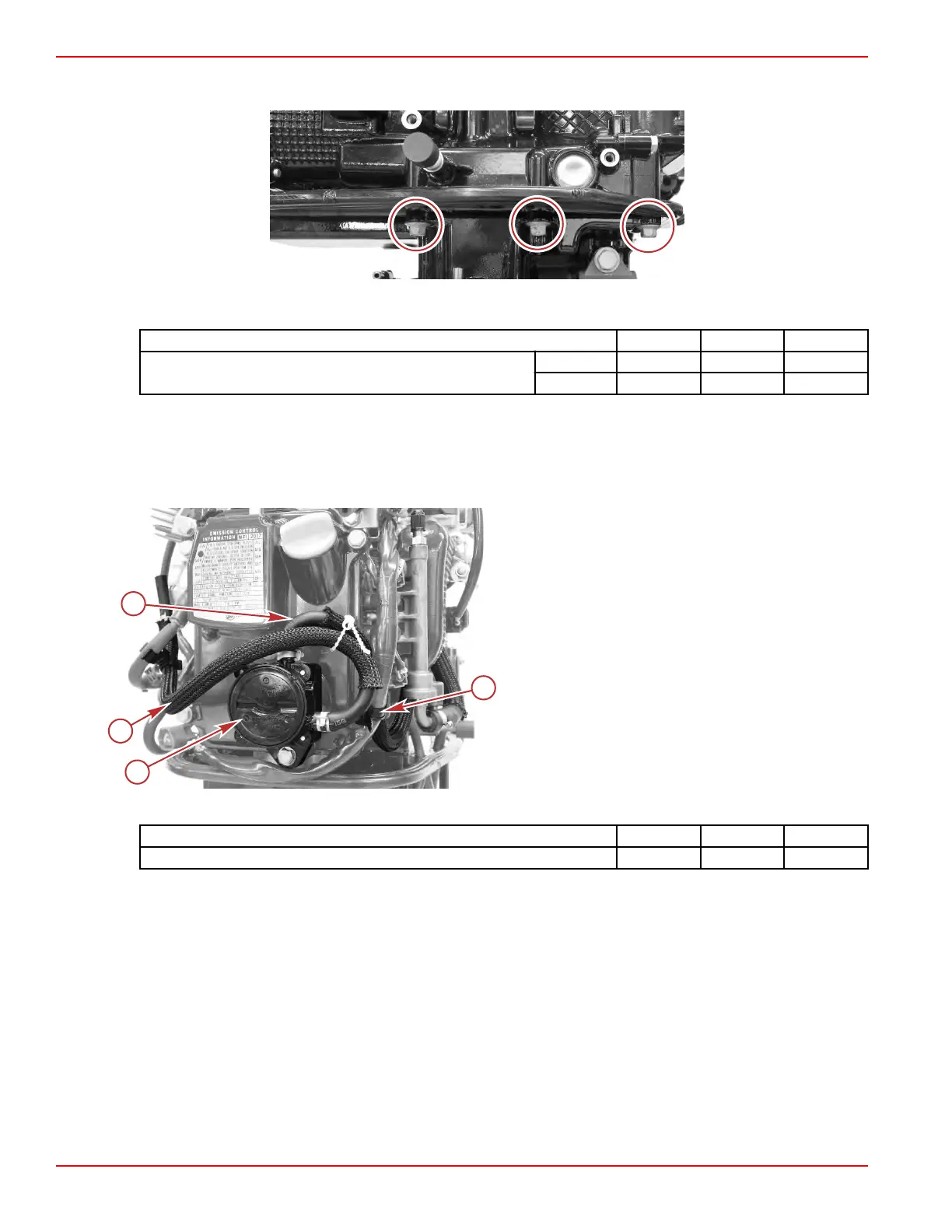
Powerhead screws (three on each side, starboard shown)
Description Nm lb‑in. lb‑ft
Powerhead screws (M8 x 35)
First 15.0 132.7 –
Final 30.0 – 22.1
2. Install the fuel system components onto the engine:
a.
Install the vapor separator tank and the fuel rail. Refer to Section 3C ‑ VST Installation and Section 3C ‑ Fuel Rail
Installation.
b.
Connect the fuel hoses to the fuel pump. Secure the connections with hose clamps.
c. Secure the fuel outlet hose to the engine harness with the reusable cable tie.
a - Fuel pump
b - Fuel pump inlet hose (from fuel filter)
c - Fuel pump outlet hose (to VST)
d - Reusable cable tie
d. Install the fuel filter bracket using one screw and washer. Tighten the screw to the specified torque.
Description Nm lb‑in. lb‑ft
Fuel filter bracket screw 6.0 53.1 –
e. Install the fuel filter onto the bracket.
f.
Connect the fuel filter outlet hose to the fuel filter. Secure the connection with a hose clamp, and secure the hose to
the upper spark plug lead with a clip, as shown.
Cylinder Block/Crankcase
Page 4A-34 © 2018 Mercury Marine 90-8M0125265 eng NOVEMBER 2017
 Loading...


