g. Connect the fuel inlet hose to the fuel filter. Secure the connection with a hose clamp. Route the hose to the front of
the engine and attach it to the engine harness with a cable tie, as shown—do not tighten the cable tie. Secure the
hose to the upper spark plug lead with a clip, as shown.
Electric start, power tilt model
shown, other models similar
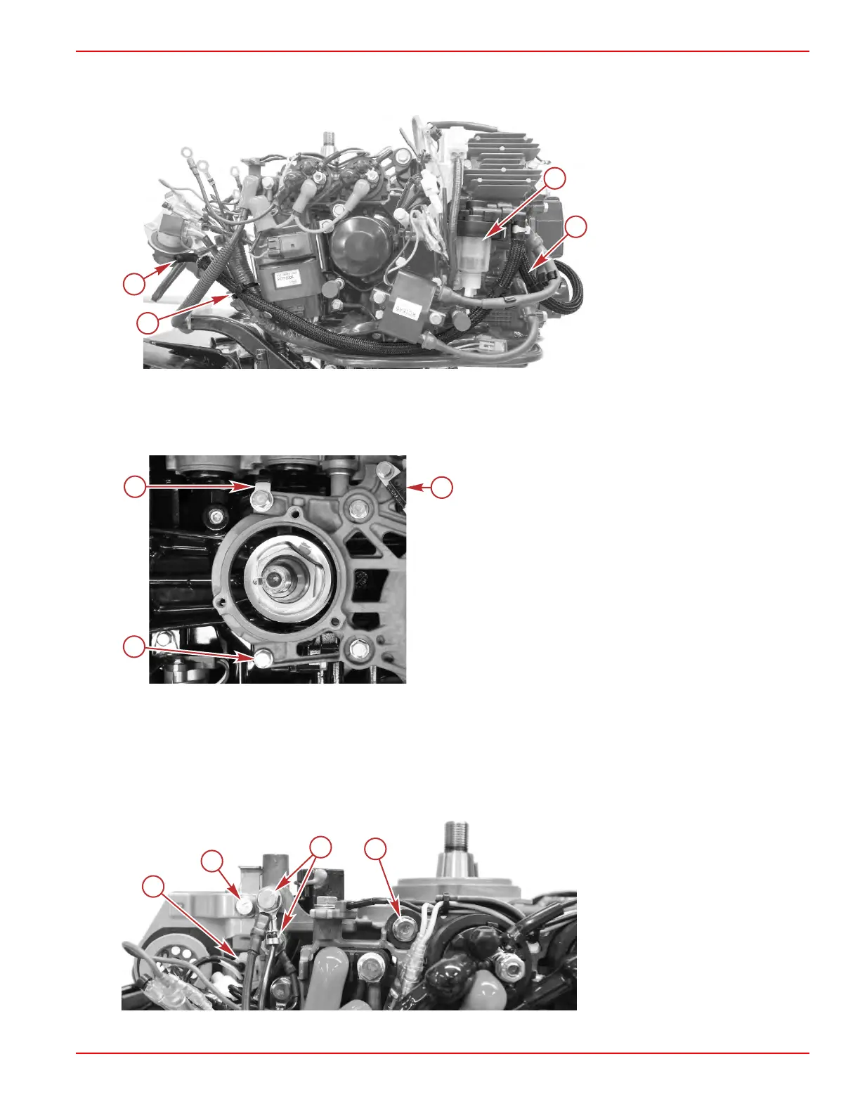
a - Cable tie
b - Fuel inlet hose
c - Fuel filter
d - Fuel filter outlet hose
3.
Install the throttle and shift linkage. Refer to Section 7A ‑ Throttle and Shift Linkage.
4. Install the stator/starter bracket:
a. Secure the bracket to the top of the engine, using four screws with washers. Ensure that the J‑clip for securing the
stator leads is in place, as shown.
a - Screw and washer (4 each)
b - J‑clip (to secure stator leads)
c - Crankshaft position sensor
b. Attach the relay/solenoid bracket to the side of the stator/starter bracket with one screw and washer. Tighten all five
screws to the specified torque.
c.
Connect the four engine harness ground terminals to the stator/starter bracket, using two screws and washers.
Tighten the screws to the specified torque.
d. Install the 14‑pin connector bracket onto the stator/starter bracket, using one screw and washer. Tighten the screw to
the specified torque.
e. Connect the crankshaft position sensor (CPS) to the engine harness.
a - CPS connector
b - Screw and washer for the 14‑pin
connector bracket
c - Screws and washers for ground
terminals (2 each)
d - Screw and washer securing relay
bracket to stator/starter bracket
Cylinder Block/Crankcase
90-8M0125265 eng NOVEMBER 2017 © 2018 Mercury Marine Page 4A-35
 Loading...


