Description Nm lb‑in. lb‑ft
Stator/starter bracket screws (5 ‑ 4 top, 1 side) 6.0 53.1 –
Engine harness ground screws (2) 6.0 53.1 –
14‑pin connector bracket screw 6.0 53.1 –
5. On electric start models:
a.
Install the starter motor. Refer to Section 2B ‑ Starter Motor Installation.
b.
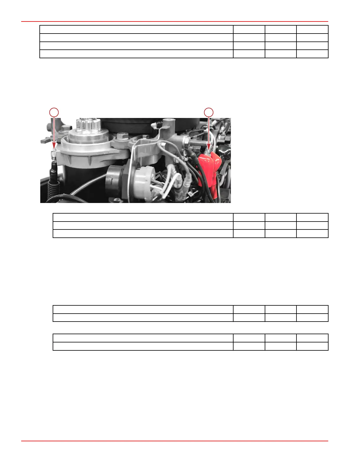
Connect the negative battery cable to the starter motor and the positive battery cable to the starter solenoid. Tighten
the screws to the specified torque.
NOTE: Ensure that the fuse lead and tilt relay lead are also connected to the starter solenoid and that all three wires
are routed through and covered by the red plastic boot.
a - Negative battery connection at
the starter motor
b - Positive battery connection at the
starter solenoid
Description Nm lb‑in. lb‑ft
Negative battery cable screw (M6 x 12) 6.0 53.1 –
Positive battery cable screw (M6 x 10) 6.0 53.1 –
6. Install the following components on the top of the powerhead:
a.
Stator. Refer to Section 2A ‑ Stator.
•
Route the stator wires under the J‑clip and beneath the relay bracket.
• Secure the harness wires to the electrical bracket with the reusable cable tie.
• Pass a second cable tie through the two slots at the bottom of the electrical bracket and around the harness
wires. Cinch the cable tie to secure the wires.
b.
Flywheel. Refer to Section 2A ‑ Flywheel.
c. Engine lifting eye. Tighten the screw to the specified torque.
Description Nm lb‑in. lb‑ft
Engine lifting eye screw 13 115 –
d. Three cowl standoffs. Tighten the standoffs to the specified torque and cover them with rubber bumpers.
Description Nm lb‑in. lb‑ft
Cowl standoffs (3) 6.0 53.1 –
e.
Camshaft gear cover. Refer to Section 3C ‑ Camshaft Gear Cover/V
ent Tank. Be certain to attach the three hoses
to the proper ports on the vent tank.
f.
Air box and recoil assembly. Refer to Section 8A ‑ Recoil Starter Installation and Section 3C ‑ Air Box
Installation.
IMPORTANT: Be certain to install the neutral interlock cable onto the recoil starter assembly and to connect the
crankcase breather hose to the valve cover.
7. Install the remote control harness and cables when applicable.
8.
Install the front cowl. Refer to Section 5A ‑ Front Cowl. Be certain to secure the fuel hose to the fitting in the front cowl.
9.
Install the driveshaft housing covers. Refer to Section 5A ‑ Driveshaft Housing Covers.
10.
Add 10W‑30 4‑Stroke Marine Engine Oil to the crankcase to the recommended fluid level. Refer to Section 1B ‑ Filling
the Crankcase with Oil.
Cylinder Block/Crankcase
Page 4A-36 © 2018 Mercury Marine 90-8M0125265 eng NOVEMBER 2017
 Loading...


