Connecting Rod Oil Clearance
Measure the connecting rod oil clearance using the measurement steps outlined following.
Connecting Rod
Oil clearance 0.015–0.041 mm (0.0006–0.0016 in.)
Connecting Rod Oil Clearance Measurement
IMPORTANT: Do not interchange connecting rod caps. Reinstall connecting rod caps in their original positions.
1.
Clean all the oil from the connecting rod bearing surfaces and connecting rod journals on the crankshaft.
2. Install the connecting rod to the crankshaft.
IMPORTANT: Install connecting rods in their original locations. Make sure that the "UP" mark on the connecting rod cap
faces towards the flywheel end of the crankshaft.
3. Place a piece of gauging plastic on the crankpin journals.
NOTE: Do not put the gauging plastic over the oil hole in the bearing surface of the crankshaft.
a - Gauging plastic
b - Crankshaft oil hole
c - Connecting rod
4. Install the connecting rod cap and tighten the connecting rod cap bolts to specification.
IMPORTANT:
Do not rotate the crankshaft while performing this measurement.
Description Nm lb‑in. lb‑ft
Connecting rod cap bolt
First
6.0 53.1 –
Final
10.0 88.5 –
5. Remove the connecting rod cap.
6.
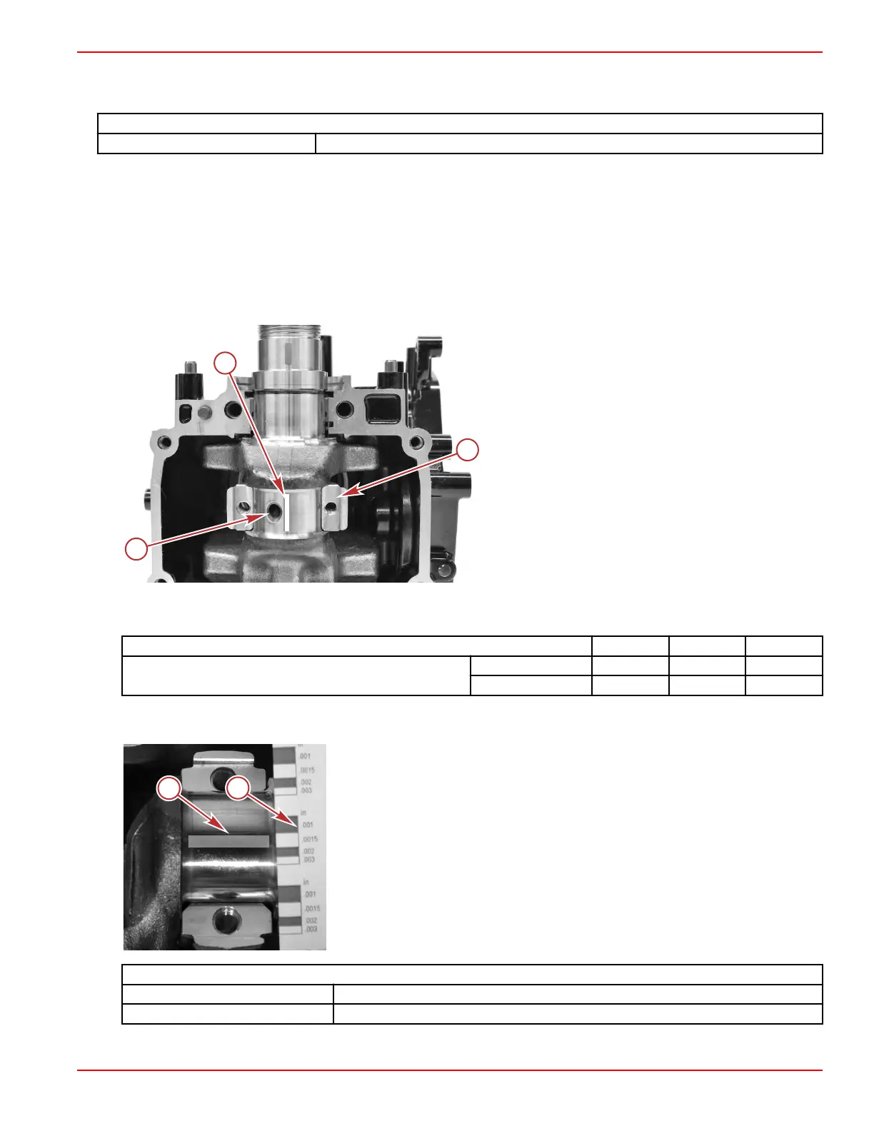
Measure the gauging plastic at its maximum compressed width.
a - Compressed gauging plastic
b - Gauging plastic scale
Connecting Rod
Oil clearance 0.015–0.041 mm (0.0006–0.0016 in.)
Service limit 0.060 mm (0.002 in.)
Cylinder Block/Crankcase
90-8M0125265 eng NOVEMBER 2017 © 2018 Mercury Marine Page 4A-23
 Loading...


