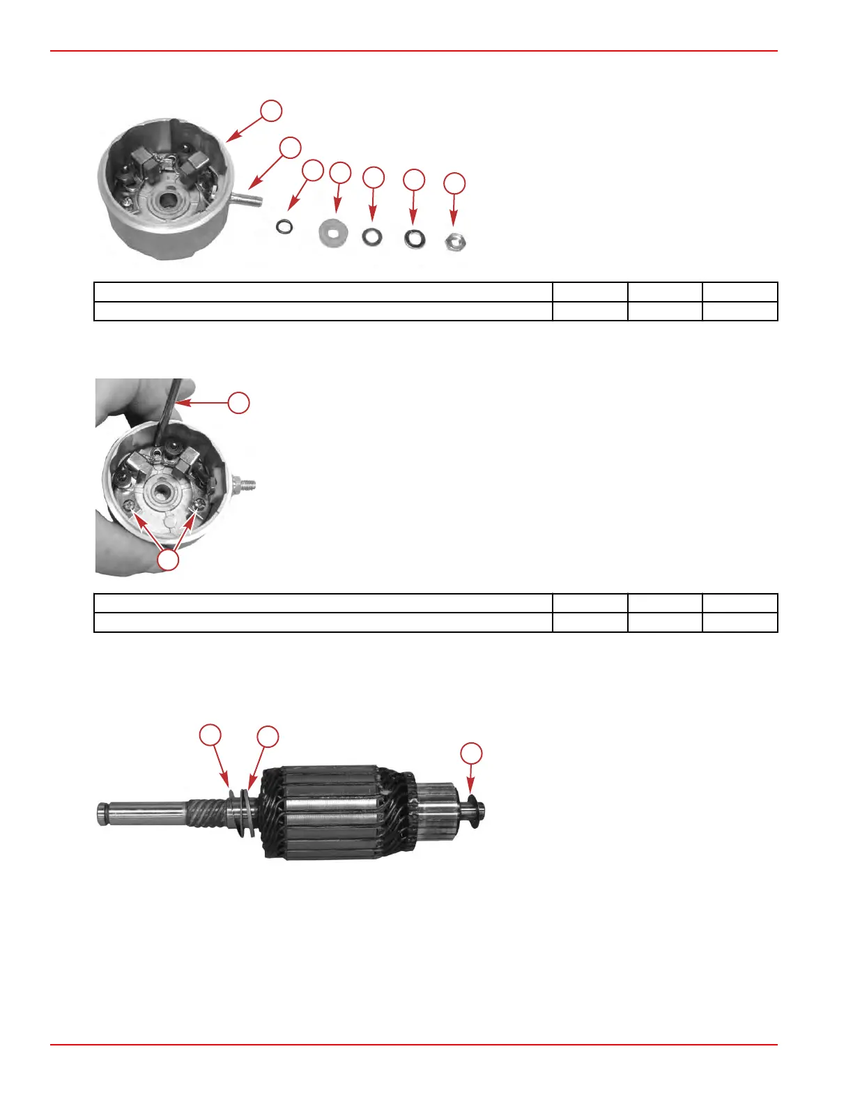
4. Assemble the power stud O‑ring, insulator, washer, lockwasher, and nut onto the power stud. Tighten the nut to the
specified torque.
a - End cap
b - Power stud
c - Power stud O‑ring
d - Insulator
e - Washer
f - Lockwasher
g - Power stud nut
Description Nm lb‑in. lb‑ft
Power stud nut 4.0 35.4 –
5. Insert a starter assembly screw through the end cap to ensure the brush card alignment.
6.
Tighten the brush card screws to the specified torque. Remove the screw from the end cap.
a - Starter assembly screw
b - Brush card screw
Description Nm lb‑in. lb‑ft
Brush card screw (2) 1.5 13.3 –
7. Install the top thrust washer and shims onto the armature.
IMPORTANT:
The thrust washer must be installed first onto the armature. The shims must be between the end cap and
the thrust washer.
8. Install the bottom thrust washer onto the commutator end of the armature.
a - Top end cap shims
b - Top thrust washer
c - Bottom thrust washer
9. Push the brush in and insert a 2.6 mm (0.093 in.) drill bit between the brush spring and the brush card. This will hold the
spring and brush for the insertion of the armature into the end cap.
Charging and Starting Systems
Page 2B-16 © 2018 Mercury Marine 90-8M0125265 eng NOVEMBER 2017
 Loading...


