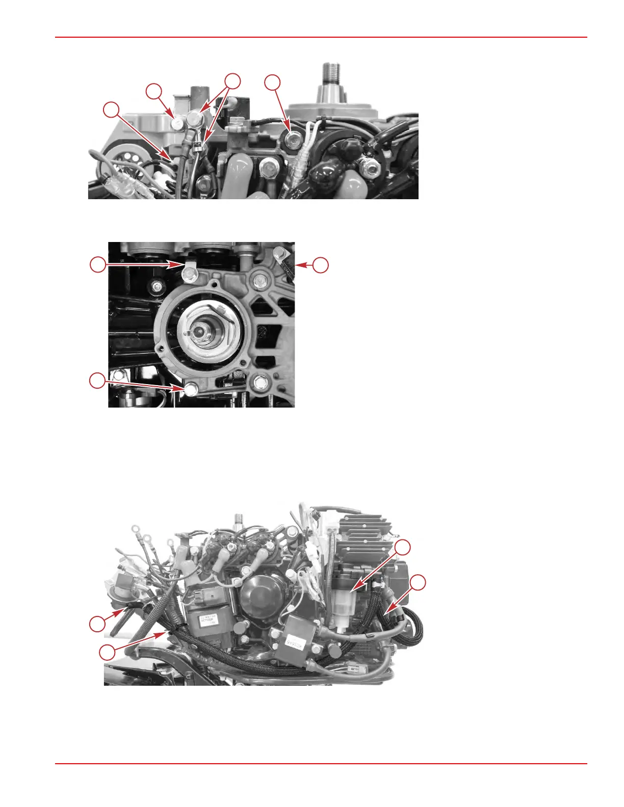
d. Remove the one screw and washer that secures the relay bracket to the stator/starter bracket.
a - CPS connector
b - Screw and washer for 14‑pin
connector bracket
c - Screws and washers for ground
terminals (2 each)
d - Screw and washer securing relay
bracket to stator/starter bracket
e. Remove the four screws and washers that secure the stator/starter bracket to the powerhead, and remove the stator/
starter bracket.
a - Screw and washer (4 each)
b - J‑clip (to secure stator leads)
c - CPS
8. Remove the timing belt.
9.
Remove the remaining throttle and shift linkage. Refer to Section 7A ‑ Throttle and Shift Linkage.
10.
Remove the fuel system components from the engine:
a. Cut the cable tie securing the fuel inlet hose to the engine harness.
b. Disconnect the inlet hose from the fuel filter, and remove the inlet hose from the engine.
c. Disconnect the outlet hose from the fuel filter. Remove the fuel filter.
Electric start, power tilt model
shown, other models similar
a - Cable tie
b - Fuel inlet hose
c - Fuel filter
d - Fuel filter outlet hose
d. Remove one screw to remove the fuel filter bracket.
e.
Remove the fuel hoses from the fuel pump.
Cylinder Block/Crankcase
90-8M0125265 eng NOVEMBER 2017 © 2018 Mercury Marine Page 4A-9
 Loading...


