5. Remove the yellow fuse housing from the electrical bracket and the black fuse housing from its pocket on the ECM.
NOTE: If you are servicing the cylinder head only, steps 6 through 11 may be skipped.
6. Remove the rubber boot from the oil pressure switch, and remove the single screw that secures the ring terminal to the
switch.
7. Remove a single screw to remove the ground terminal from the engine block.
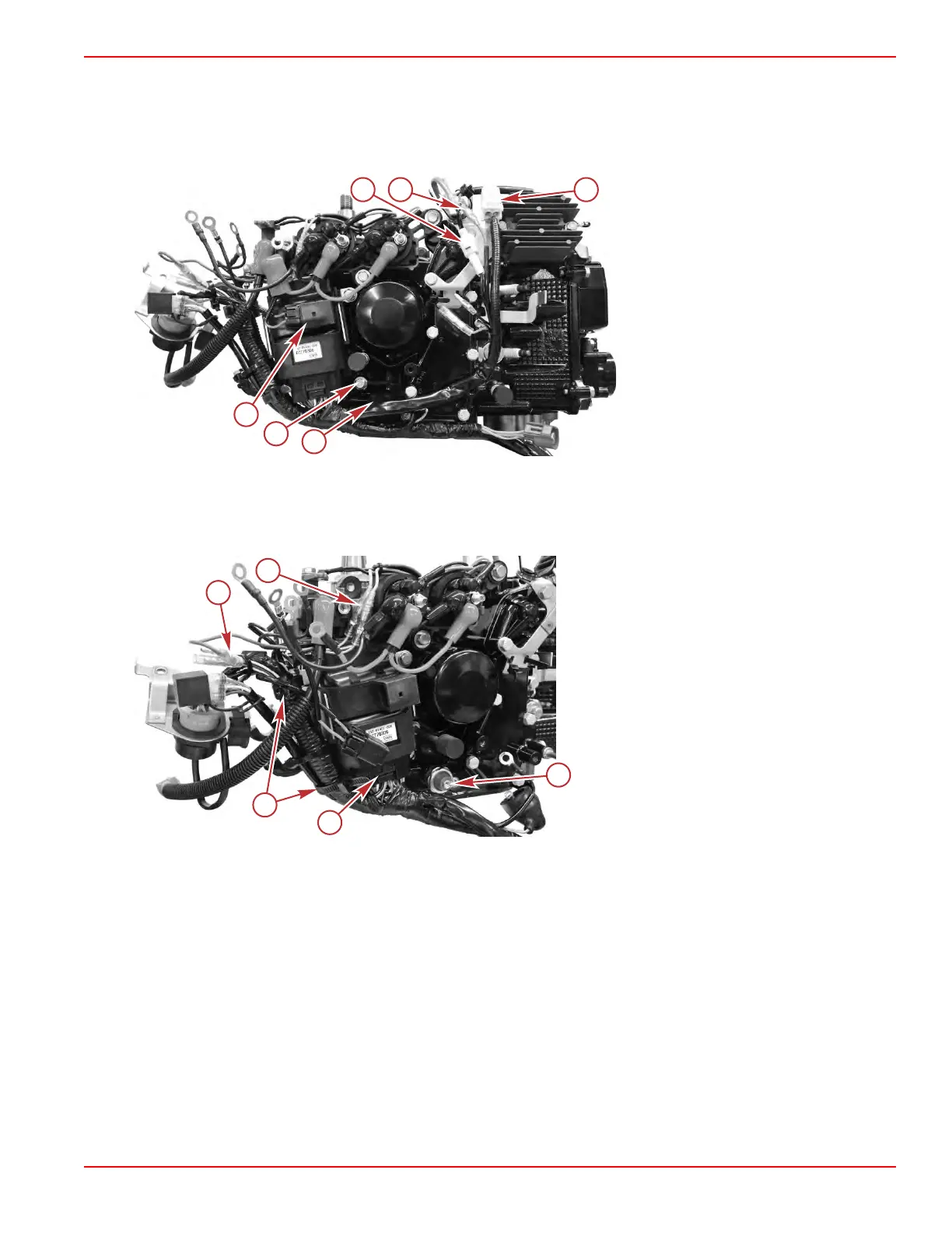
a - 2‑pin ECT sensor connector
b - Voltage regulator/rectifier red bullet
connector
c - Yellow fuse housing
d - Oil pressure switch (behind harness)
e - Ground terminal
f - Black fuse housing
8. Disconnect the ECM from the harness.
9.
Power tilt models: Disconnect the pink, light blue, and green bullet connectors.
10. Release the reusable cable ties securing the engine harness, and remove the harness from the engine.
IMPORTANT: Do not cut the reusable cable ties.
a - ECM connector
b - Reusable cable ties ‑ do not cut
c - Start solenoid green bullet connector
d - Power tilt pink and light blue bullet
connectors
e - Oil pressure switch, rubber boot and ring
terminal removed
11. Remove the ECM from its bracket, and remove two screws to remove the bracket from the engine.
Cylinder Block/Crankcase
90-8M0125265 eng NOVEMBER 2017 © 2018 Mercury Marine Page 4A-11
 Loading...


