• Main bearing surfaces on the cylinder block and crankcase cover
•
Main bearings
• Crankshaft bearing surfaces
3. Install the main bearing halves into the cylinder block.
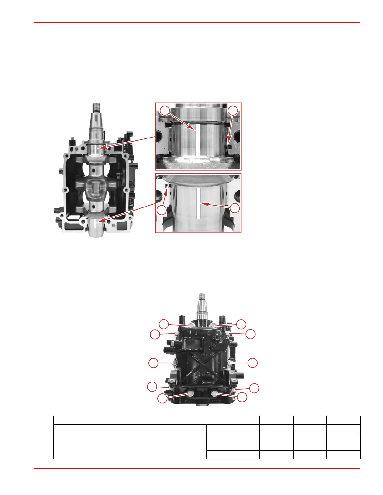
NOTE: Align each bearing projection with the notch in the cylinder block.
4. Install the crankshaft onto the cylinder block.
5. Place a piece of gauging plastic onto each of the crankshaft bearing surfaces.
NOTE: Do not put gauging plastic over the oil hole on the bearing surface of the crankshaft.
a - Gauging plastic
b - Bearing projection in the cylinder block
notch
6. Install the bearing halves into the crankcase cover.
NOTE: Align each bearing projection with the notch in the crankcase cover.
7. Install the crankcase cover onto the cylinder block.
8. Lightly lubricate the main bearing bolts and crankcase cover bolt threads with clean engine oil. Tighten the bolts to the
specified torque in sequence in two steps.
IMPORTANT: Do not move the crankshaft until the measurement process has been completed.
1
2
3
4
5
6
7
8
9
10
64052
1
2
3
4
5
6
7
8
9
10
Description Nm lb‑in. lb‑ft
Main bearing bolts (1–4) (M8 x 50)
First
10.0 88.5 –
Final
23.5 – 17.3
Crankcase cover bolts (5–10) (M6 x 30)
First
6.0 53.1 –
Final
11.5 101.8 –
Cylinder Block/Crankcase
90-8M0125265 eng NOVEMBER 2017 © 2018 Mercury Marine Page 4A-21
 Loading...


