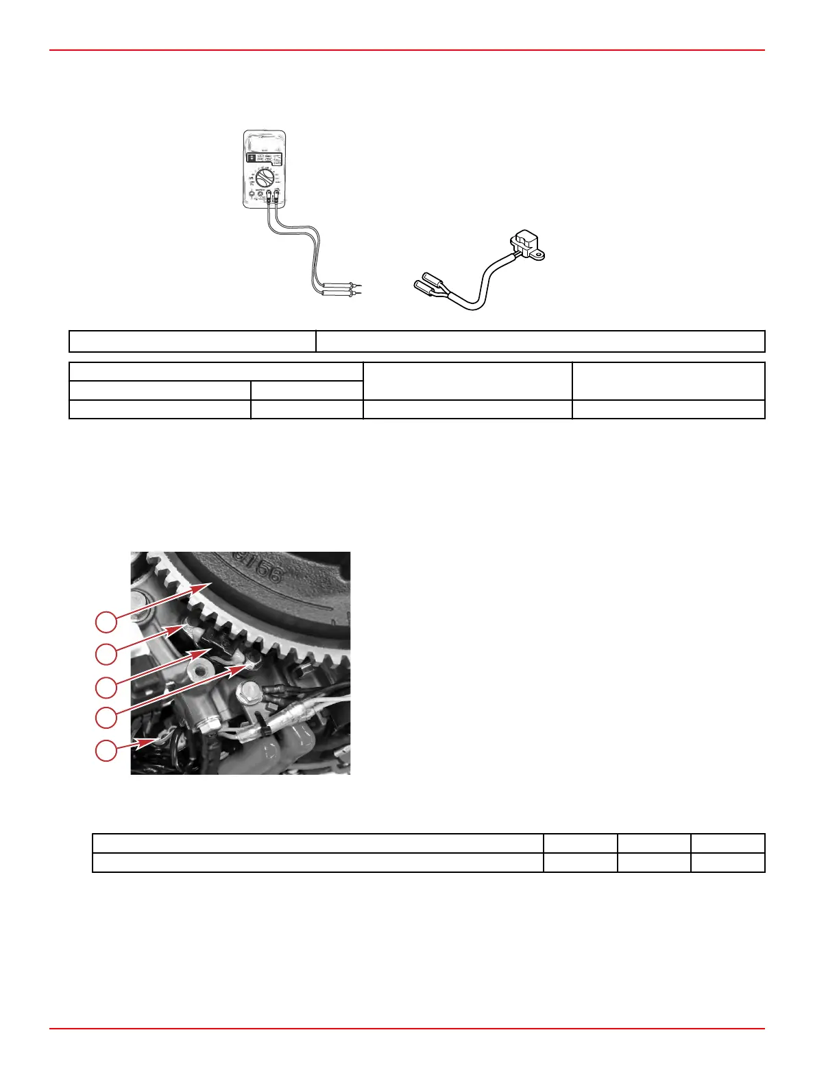
Crankshaft Position Sensor Test
With the engine not running, disconnect the CPS from the engine harness, and measure the sensor's resistance with a DMT
2004 Digital Multimeter, or equivalent.
DMT 2004 Digital Multimeter 91‑892647A01
Meter Test Leads
Meter Scale Reading
Red Black
Red/white Black Ω 148–222 Ω
CPS Removal
1.
Remove the air box and recoil starter.
• It is easiest to remove and install these two items together.
•
Refer to Section 3C ‑ Air Box Removal and Section 8A ‑ Recoil Starter.
2. Disconnect the CPS from the engine harness at the 2‑pin connector.
3. Remove the two screws that secure the CPS, and remove the CPS.
a - CPS 2‑pin connector
b - Screw (2)
c - CPS
d - Flywheel
CPS Installation
1.
Secure the CPS to the engine with two screws. Tighten the screws to the specified torque.
Description Nm lb‑in. lb‑ft
CPS screws 3.0 26.6 –
2. Connect the CPS to the engine harness at the 2‑pin connector.
3.
Install the air box and recoil starter assembly.
• It is easiest to install the recoil starter and air box together.
•
Refer to Section 8A ‑ Recoil Starter and Section 3C ‑ Air Box Installation.
Ignition
Page 2A-6 © 2018 Mercury Marine 90-8M0125265 eng NOVEMBER 2017
 Loading...


