112
9−4−4.
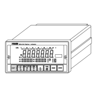
Pin configuration on terminal board and their connections
(1)
Pin configuration
SDA Differential output(+)
SDB Differential output(−)
RDA Differential input(+)
RDB Differential input(−)
TRM Cable end resistance
S.G. Signal ground
(2)
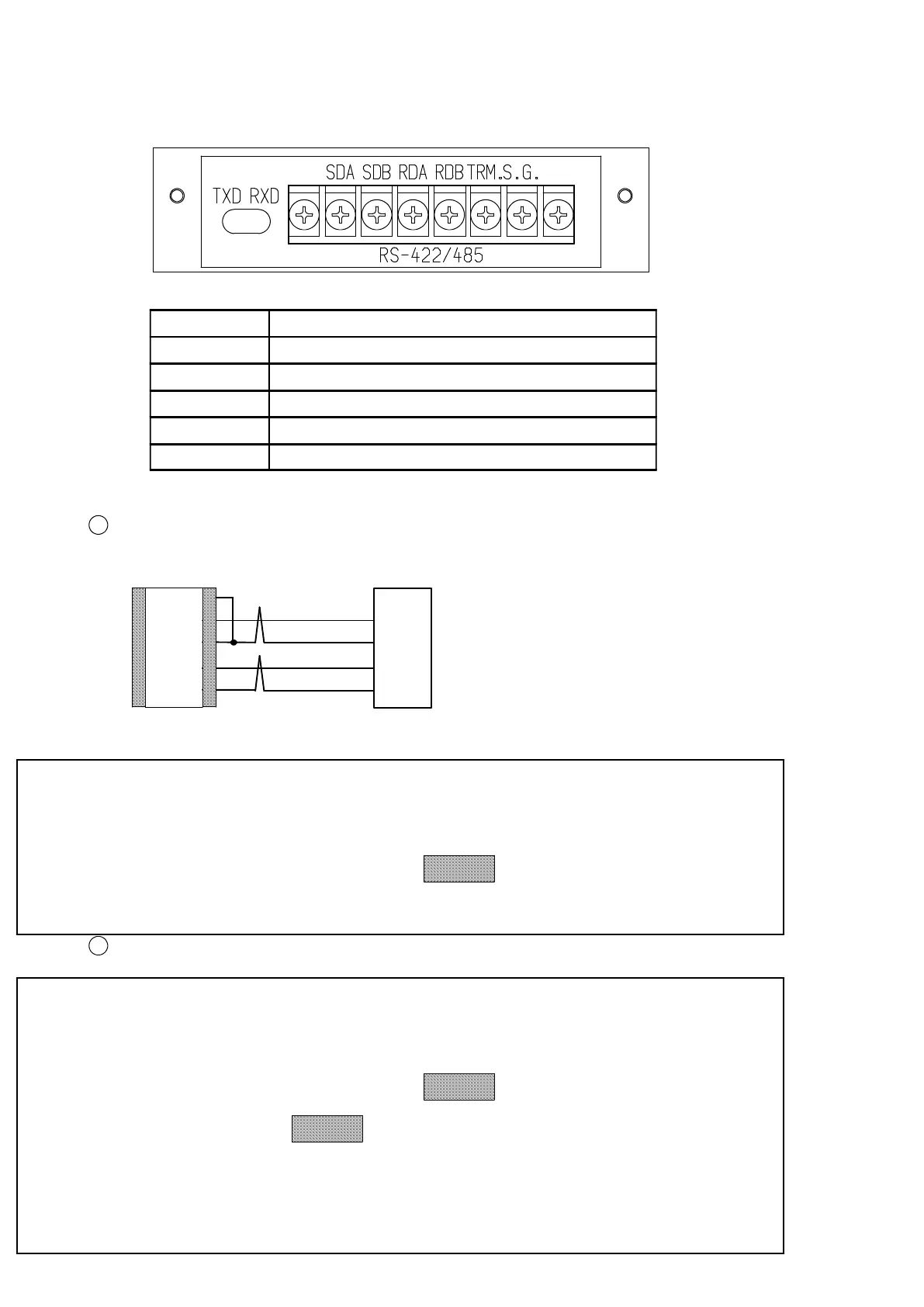
Connecting Example 1
1
1 vs 1
RDA
RDB
SDA
SDB
SDA
SDB
RDA
RDB
CSD−814B
TRM
Host
● For the connections between the instruments, twisted pair wire is
recommended.
● To execute a termination at
section, shorten between RDB
and TRM located on the terminal board.
2
1 vs n (n = 2 to 10)
● For the connections between the instruments, twisted pair wire is
recommended.
● To execute a termination at
section, shorten between RDB
and TRM at
section on CSD−814B terminals.