160
13.
Appendix
13−1. Replacement of fuse
Warning ● When installation method for the fuse is wrong and/or capacity of
installed fuse is inadequate, it causes an unexpected faulty of the
instrument.
1
Set OFF the power supply for the instrument.
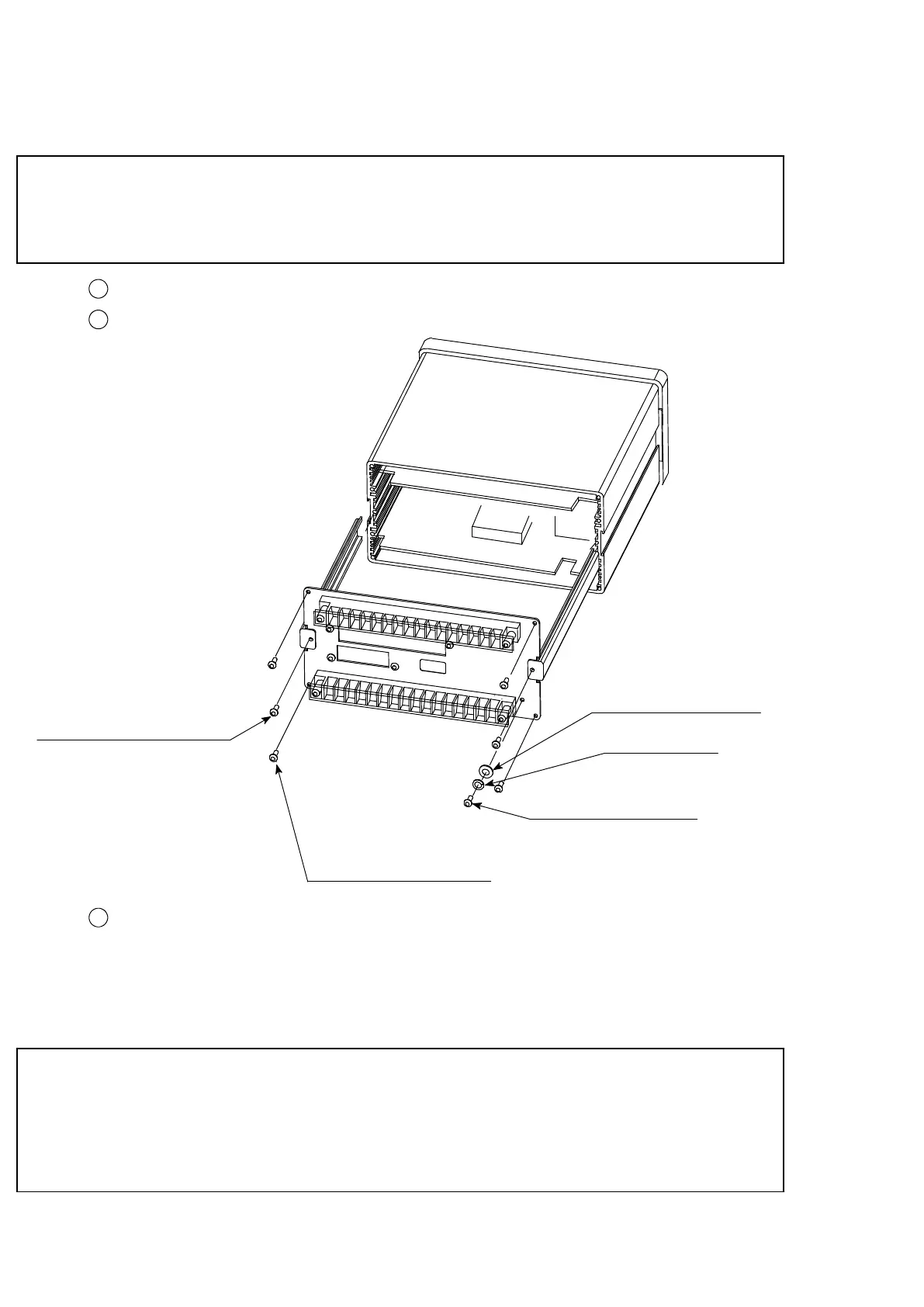
2
Remove the 7 pieces of screws on the rear panel.
+Cross recessed pan
head screw. M3 × 10
Spring washer
Toothed lock washers
4−+Cross recessed pan
head screw M3 × 6
2−+Cross recessed binding
head screw M3 × 15
3
Draw out the contents of the instrument by holding the rear panel to the arrow marked
direction slowly.
Whichever option among “Current output”, “Voltage output”, “BCD output”, “RS−232C
Interface”, “RS−422 Interface”, “Serial Interface” and “Digi−Switch Interface” is installed,
remove the connector which has connected with the optional P.C. board.
● When drawing out the rear panel to the arrow marked direction, it is
difficult to do. Because the upper and lower P.C. boards are inserted
into the terminal board with cartridge method.
Care should be taken when you work.