39
7−1−2.
Contact output signal
Terminal No. Name Operation
⑨
RUN
When the instrument is in the Measurement mode, connection can be
available. Open when CHECK is OK. 1a contact.
⑩
S0
By the setting function FUNC−13, operation can be made in either
condition as below:
a) Connects when the load display is more than the maximum display
value.
b) Connects when selected 2 contact outputs among S1, S2, S3 and S4 are
OFF(open).
⑪
S1 Contact output for comparator S1. 1a contact.
⑫
S2 Contact output for comparator S2. 1a contact.
⑬
S3 Contact output for comparator S3. 1a contact.
⑭
S4 Contact output for comparator S4. 1a contact.
⑮
ERROR
Connects when various kinds of error(s) occurred, or power supply for the
instrument is OFF. 1b contact
⑯
COM. 2 Common for contact output(Terminal No.⑨~⑮).
● COM. 1(Terminal No.7) and COM. 2(Terminal No.16) are isolated.
● Delay time from completing every output condition and contact
output ON will be 50 ms approximately.
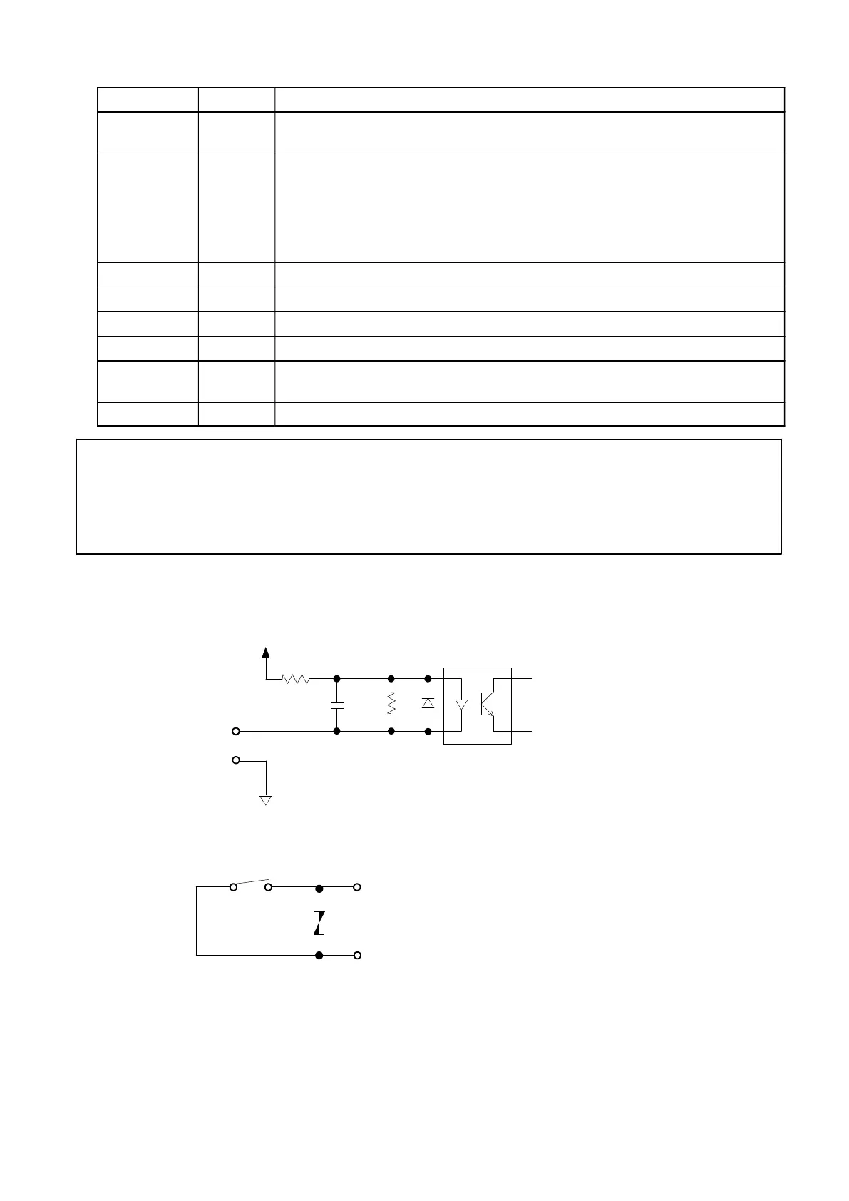
7−1−3.
Equivalent circuit
(1)
External control input section
+12 V
430 Ω
ΩΩ
Ω
INPUT
COM. 1
0.047 μ
μμ
μ
2.2 kΩ
(2)
Contact output section
OUTPUT
COM. 2
AC125 V 0.1 A
DC30 V 0.5 A