151
11.
Specifications
11−1. Specifications for analog
・ Bridge power supply DC10 V±0.3 V within 120 mA (DC2.5 V and 5 V are changeable.)
Remote sensing applied.
・ Applicable transducers Up to 4 pieces of strain gages applied transducers(350 Ω) can be
connectable.
・ Input range F.S. setting can be made with input range from 0.3 mV/V to 3 mV/V.
(At the time of bridge power supply is DC10 V)
±F.S. setting can be available
with input range from ±0.6 mV/V to ±3 mV/V
(At the time of selection of +/− Display Mode at Function setting.)
(At the time of bridge power supply is DC10 V)
・ Zero point adjustment range ±2.4 mV/V
・ Non−Linearity 0.01 %F.S.
・ Temperature coefficient
Zero point ±0.2 μV/℃(Input conversion)
Sensitivity ±0.001 5 %F.S./℃
・ A/D sampling 100 times/s
・ CHECK Approx. 0.3 mV/V 1 point
※ Suitable Extension cable is Minebea’s standard cable CAB−501
(6−cores) within 100 m
※ Not applicable when Zener barrier is used.
11−2. Specifications for digital
・ Load display
Display range −1 000 to 11 000(×2, ×5 and ×10 can be available.)
−11 000 to 11 000(×2, ×5 and ×10 can be available when +/−
display mode is set with the Function setting.)
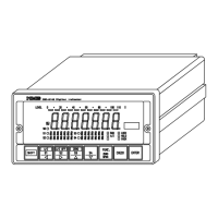
Display 7 segment green colored fluorescence display tube with 22 mm
character height.
Over display “−OL” display at the time of minus (−) over, and “OL” display
at the time of plus (+) over.
・ Condition display RUN, A/Z(Auto Zero), LOCK, HOLD, CHECK
・ Setting display 7 segment fluorescence display tube.
Each 7 digits of S1, S2, S3 and S4 with 4.5 mm character height.
・ Judgement display S0, S1, S2, S3 and S4
・ Bar meter display Displays the percentage of present load against rated capacity
(100 %) by 11 dots bar meter display.
・ Display times 4 times/s(20 times/s can be available depending on the setting.)
・ Decimal point display 10
1
, 10
2
, 10
3
and 10
4
(Changeable)