161
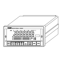
Connector
Connector
4
After the connector is removed according to ③, draw out the rear panel from the case further.
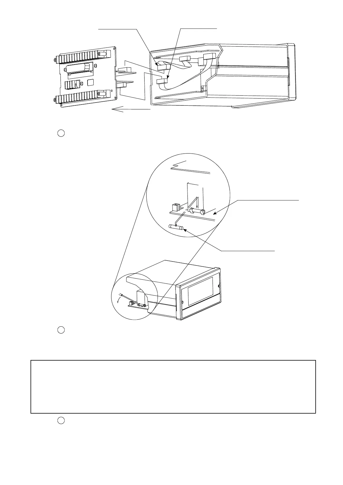
And replace the fuse installed on the lower side of P.C. board.
Time lag fuse 1 A
Lower side P.C. board
5
After replacing the fuse, insert the rear panel into the case. In case that option has installed,
connect the connector with the option individually, and after that insert the rear panel from
the arrow marked direction to adjust P.C. board to the terminal board firmly.
Warning ● When installing the rear panel into the case, care should be taken not
to insert the cable between the P.C. board and terminal board.
If inserted, it may have the failure and/or destruction on the
instrument due to cutting the cable and so on.
6
Remove the 7 pieces of screws on the rear panel.