141
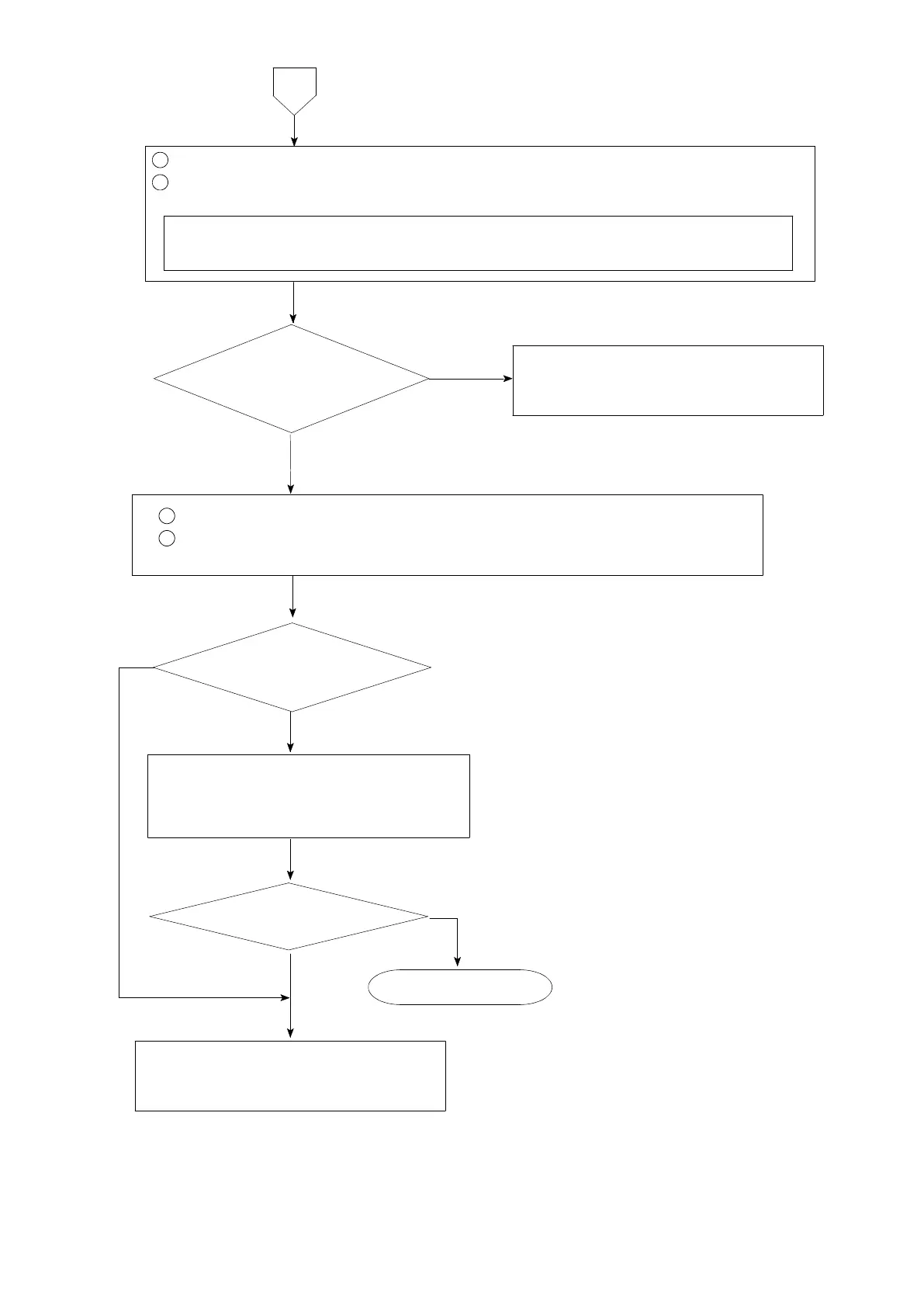
Set the connecting range to DC ・ V for the measuring instrument such as tester
and so on.
1
Remove the connecting cable for sensor from rear panel terminal board.
2
Measure the voltage between the terminals of A and C after shortening the terminals
between A−F and C−G on the rear panel terminal board.
The display becomes stable
in an optional value.
The voltage between
A and C is stable and same as
the setting of FUNC−55.
8
Check the condition of various kinds of
connections according to the section 4.
Check if there are effects from the noise
source from inverter and so on especially.
Start measurement.
Same condition
NO
YES
1
Short between B−D and A−G on rear panel terminal.
2
Set the load display to the monitoring condition on the sensor according to
the paragraph 7−15.
YES
YES
Inform Minebea about the contents of
failure and situation at site in details.
NO
NO
Inform Minebea about the contents of
failure and situation at site in details.