17. Interface specifications
MiR1350 User Guide (en) 05/2022 - v.1.2 ©Copyright 2021-2022: Mobile Industrial Robots A/S. 249
If you disable the feature and connect a load that has a capacity above 100 µF or
draws large currents in the first 100ms to the TOP-Safe48V pin, and you don’t
integrate your own softstarter to the device, the TOPFUSEwill trip when the
robot exits Emergency or Protective stop. The fuse will reconnect again shortly
after using the inbuilt softstarter.
NOTICE
There is a risk that the fuse will break when it is tripped. For this
reason, we recommend that you ensure your top module does not
trip the fuse as described above, even though in most cases it will
reconnect.
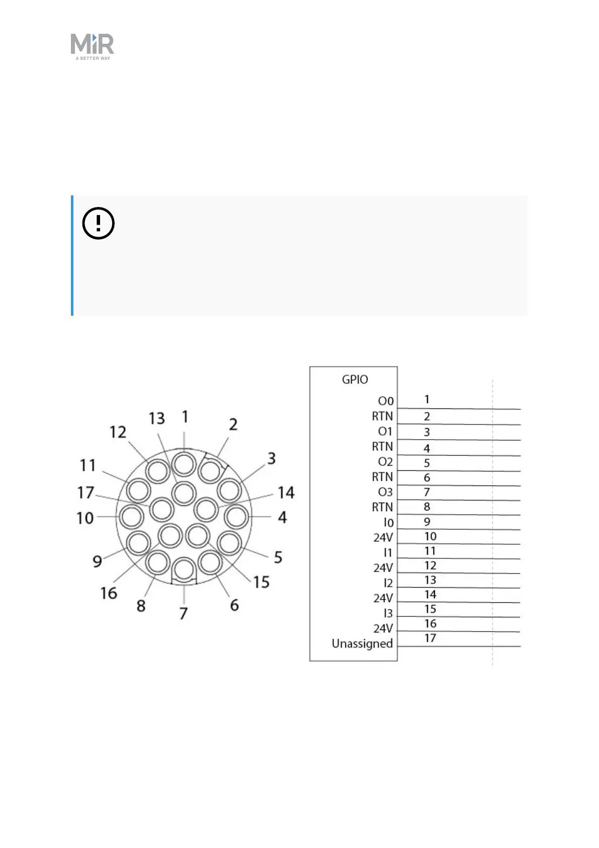
GPIO
Figure 17.3. Pin numbers: male connector viewed from the front (left) and wiring diagram (right).
The GPIO has the following pins: