2. Product presentation
MiR1350 User Guide (en) 05/2022 - v.1.2 ©Copyright 2021-2022: Mobile Industrial Robots A/S. 29
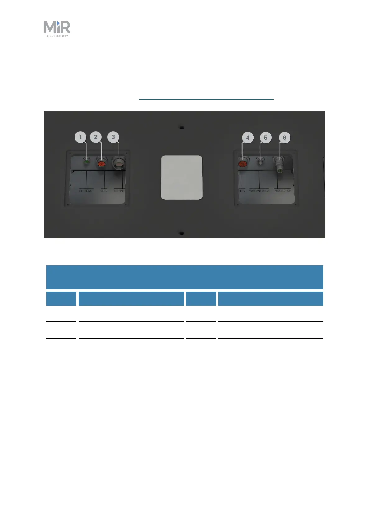
Top compartment components
The top compartments interfaces are listed in Table 2.7. For detailed information
on electrical interfaces, see Interface specifications on page243.
Figure 2.10. Interfaces in the top compartments.
Pos. Description Pos. Description
1 Ethernet 2 GPIO: General purpose I/O
3
Power
4 Auxiliary safety functions
5
WiFi antenna
6 Auxiliary emergency stop
with dummy plug
Table 2.7.
Identification of interfaces in 2.3
2.4 Manual brake release switch
The Manual brake release switch is located in the rear compartment. You release
the robot's mechanical brakes by turning the Manual brake release switch
clockwise.