F-39
FX Series PLC User's Manual - Data Communication Edition
Non-Protocol Communication (RS/RS2 Instruction)
6 Creating Programs (RS Instruction)
6.1 Checking Contents of Related Devices
A
Common Items
B
N:N Network
C
Parallel Link
D
Computer Link
E
Inverter
Communication
F
Non-Protocol
Communication
(RS/RS2 Instruction)
G
Non-Protocol
Communication
(FX
2N
-232IF)
H
Programming
Communication
I
Remote
Maintenance
Apx.
Discontinued
models
6. Creating Programs (RS Instruction)
This chapter explains how to create programs for non-protocol communication using RS instruction and how
such programs operate.
6.1 Checking Contents of Related Devices
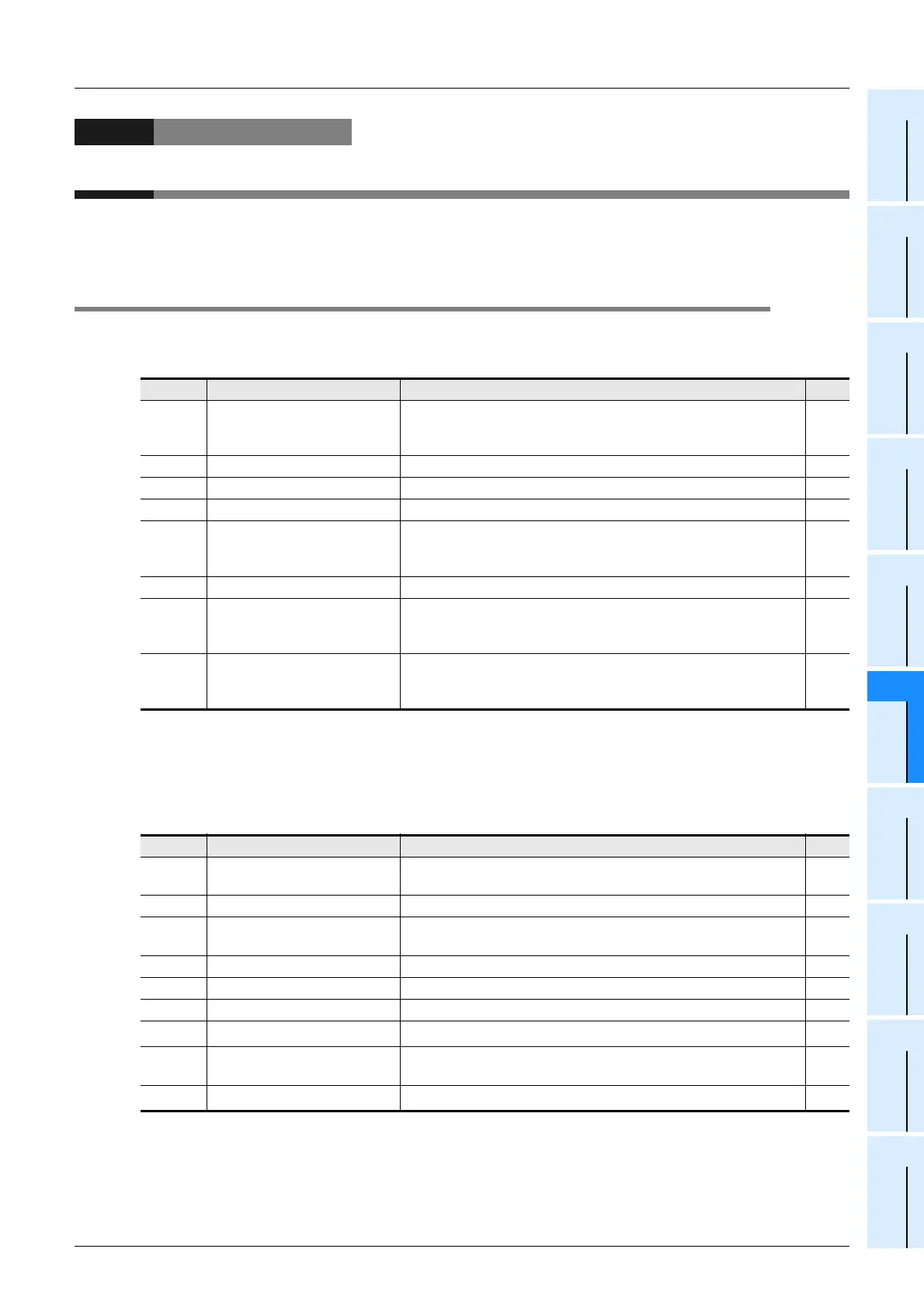
The tables below show devices used in non-protocol communication using the RS instruction.
1. Bit devices
R: Read only
W: Write only
R/W: Read or Write
*1. Not provided in FX
0N, FX2(FX), FX2C, and FX2N (before Ver. 2.00) PLCs.
2. Word devices
R: Read only
W: Write only
R/W: Read or Write
*1. Not provided in FX
0N, FX2(FX), FX2C, and FX2N (before Ver. 2.00) PLCs.
*2. Provided only in FX3U and FX3UC PLCs.
Device Name Description R/W
M8063
Serial communication error
(ch1)
This device turns ON when a communication error occurs.
When this device (serial communication error) turns ON, D8063
stores the corresponding error code.
R
M8120 Communication setting keep
This device keeps the communication setting status (for FX
0N
PLC).
W
M8121 Sending wait flag This device remains ON while the PLC is waiting to send. R
M8122 Sending request When this device is set to ON, the PLC starts to send. R/W
M8123 Receiving complete flag
This device turns ON when receiving is completed.
While this device (receiving complete flag) is ON, the PLC cannot
receive any data.
R/W
M8124 Carrier detection flag This device turns ON in synchronization with the CD signal. R
M8129
*1
Time-out check flag
This device turns ON when data receiving is suspended and the
next set of data is not given within the time set by the timeout
settings device (D8129).
R/W
M8161 8-bit processing mode
This device sets the send/receive data bit length to 16-bit or 8-bit.
ON: 8-bit mode
OFF: 16-bit mode
W
Device Name Description R/W
D8063 Error code display
When the serial communication error flag (M8063) turns ON, this
device stores the corresponding error code.
R/W
D8120 Communication format setting This device sets the communication format. R/W
D8122
Amount of data remaining to
be sent
This device stores the amount of remaining data to be sent. R
D8123 Amount of data received This device stores the amount of received data. R
D8124 Header This device sets the header (initial value: STX (H02)). R/W
D8125 Terminator This device sets the terminator (initial value: ETX (H03)). R/W
D8129
*1
Time-out time setting This device sets the timeout time. R/W
D8405
*2
Communication parameter
display
This device stores communication parameters set in the PLC. R
D8419
*2
Operation mode display This device stores the communication type being used. R
 Loading...


