A-51
FX Series PLC User's Manual - Data Communication Edition
Common Items
2 Communication Types and Communication Equipment
2.3 Combination of Communication Equipment (Block Diagram)
A
Common Items
B
N:N Network
C
Parallel Link
D
Computer Link
E
Inverter
Communication
F
Non-Protocol
Communication
(RS/RS2 Instruction)
G
Non-Protocol
Communication
(FX
2N
-232IF)
H
Programming
Communication
I
Remote
Maintenance
Apx.
Discontinued
models
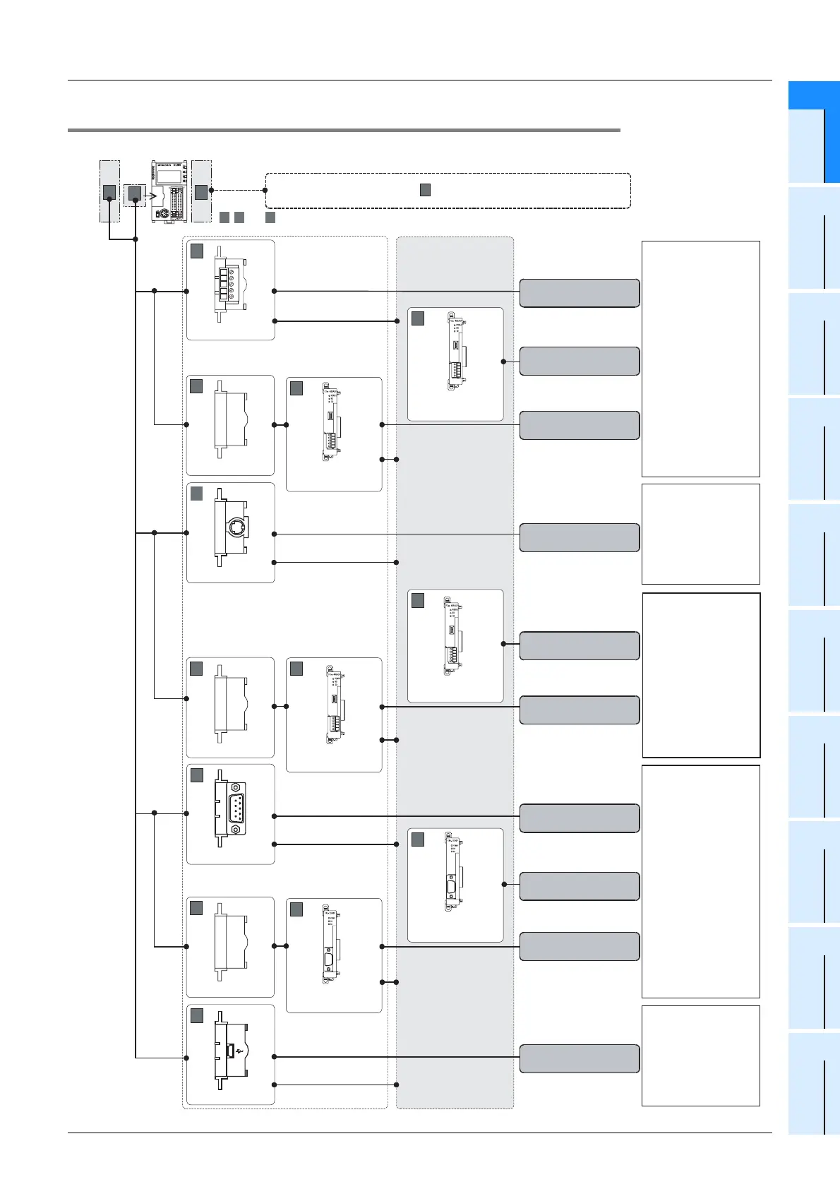
2.3.11 For FX3UC-32MT-LT(-2)
FX3UC-32MT-LT(-2)
C
B
A
N:N Network
Parallel link
Computer link
Non-protocol
communication
Inverter
communication
Programming
communication
Computer link
Non-protocol
communication
Programming
communication
Remote
maintenance
RS-485
RS-
232C
RS-422
FX3U-485-BD
B
FX3U-422-BD
B
8-pin MINI-DIN,
female
FX3U-232-BD
B
9-pin D-Sub,
male
ch1
FX3U-CNV-BD
B
FX
3U
-485ADP
(-MB)
A
ch1
FX
3U
-485ADP
(-MB)
A
ch2
European
terminal block
European
terminal block
European
terminal block
ch1
FX3U-CNV-BD
B
FX
3U
-485ADP
(-MB)
A
ch1
FX
3U
-485ADP
(-MB)
A
ch2
European
terminal block
European
terminal block
Non-protocol
communication
FX3U-CNV-BD
B
FX
3U
-232ADP
(-MB)
A
ch1
FX
3U
-232ADP
(-MB)
A
ch2
9-pin D-Sub,
male
9-pin D-Sub,
male
ch1
Programming
communication
USB
FX3U-USB-BD
B
MINI-USB B plug,
female
ch1
Either FX3U-
232ADP(-MB) or
FX
3U-485ADP(-MB)
can be selected.
For special function units/blocks , refer to the next page.
C
, and indicate the mounting position.
A B C
(For the mounting procedure, refer to the respective communication equipment manual.)
RD
RD A
RD B
SD A
SD B
SG
SD
RD
SD
RD
SD
 Loading...


