A-52
FX Series PLC User's Manual - Data Communication Edition
Common Items
2 Communication Types and Communication Equipment
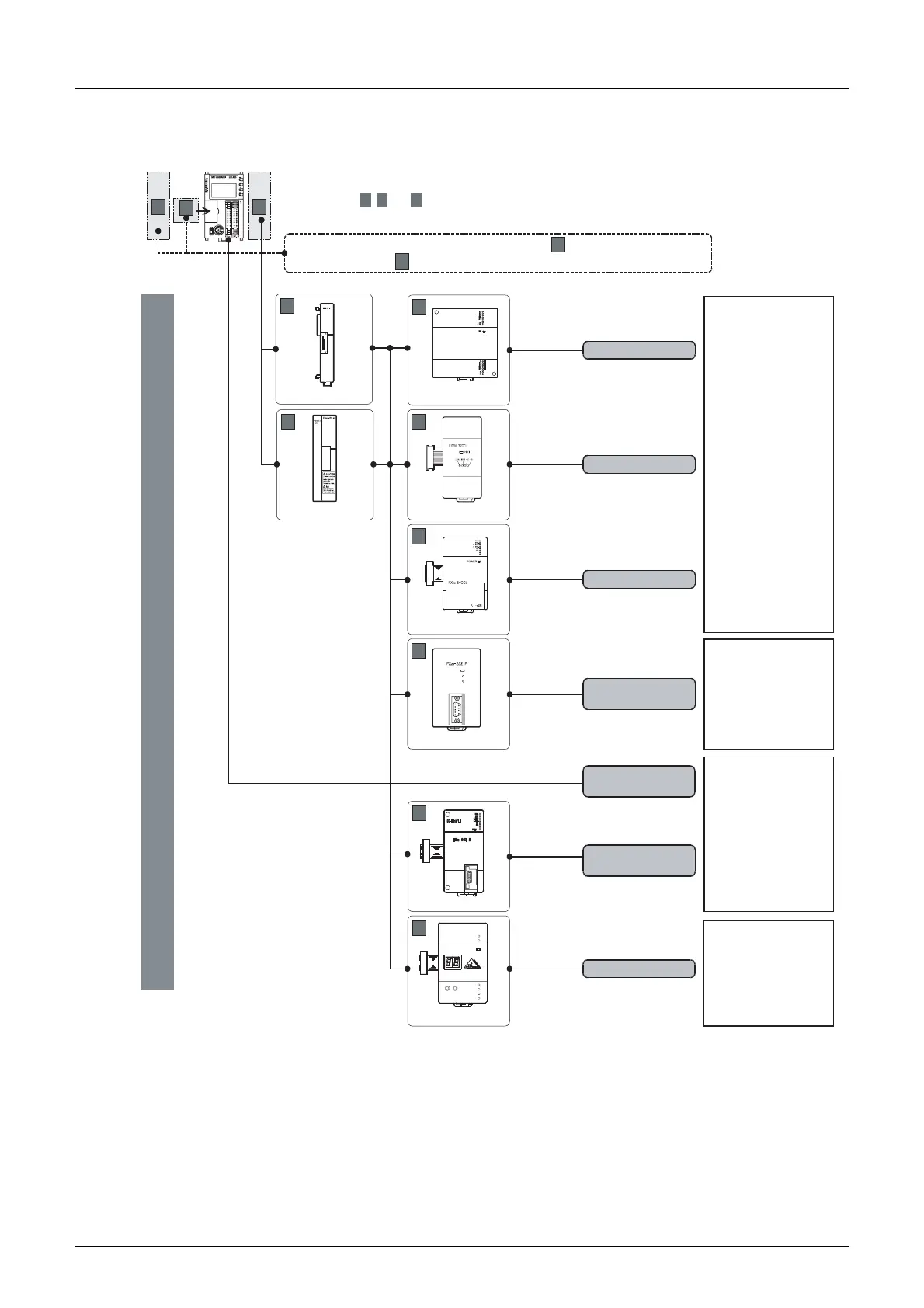
2.3 Combination of Communication Equipment (Block Diagram)
*1. The FX2N-16CCL-M and FX2N-32ASI-M cannot be used at the same time.
*2. Only one FX
3U-64CCL unit can be connected to the main unit.
Limitation in the number of connectable units
Connected special function units/blocks operate using the 24V DC or 5V DC power supply of the PLC.
Accordingly, when the total current consumption is larger than the current capacity of the PLC, it is necessary
to add the power block FX
3UC-1PS-5V.
→ For details, refer to the respective FX PLC manual.
For special adapters with communication type and communication
expansion boards , refer to the previous page.
FX3UC-32MT-LT(-2)
C
B
A
Up to 7 units can be selected.
For master
station
For remote
For intelligent
device
station
device
station
CC-Link/LT
FX2N-32CCL
C
FX3U-64CCL
C
M3.5 terminal block
M3 terminal block
M3 terminal block
Dedicated
connector
B
C
FX2NC-CNV-IF
Dedicated
connector
For FX
3UC-32MT-LT(-2)
built-in.
C
FX2N-16CCL-M
*1
*2
FX
2N
-64CL-M
C
E
R
R
O
R
CC-Link
FX2N-16CCL-M
C
FX3UC-1PS-5V
, and indicate the mounting position.
A B C
(For the mounting procedure, refer to the respective communication equipment manual.)
CC-Link
FX
2N
-32ASI-M
*1
C
FX
2N
-32ASI-M
POWE
R
U
ASI
ASI
ACTIVE
PRJ
MODE
PRG
ENABLE
FROM/
TO
CONFIG
ERR
MOD
E
SE
T
ADDRESS/
ERROR
M3 terminal block
AS-i system
A
Non-protocol
communication
FX2N-232IF
C
POWER
SD
RD
9-pin D-Sub,
male
 Loading...


