7 Before Starting Positioning Operation
47
FX3U-20SSC-H Positioning Block User's Manual
1
Introduction
2
System
configuration
3
Example
Connection
4
Installation
5
Wiring
6
Memory
configuration
and data
7
Before starting
positioning
control
8
Manual control
9
Positioning
Control
10
Table Operation
7.1 Note on Setting Parameters
5
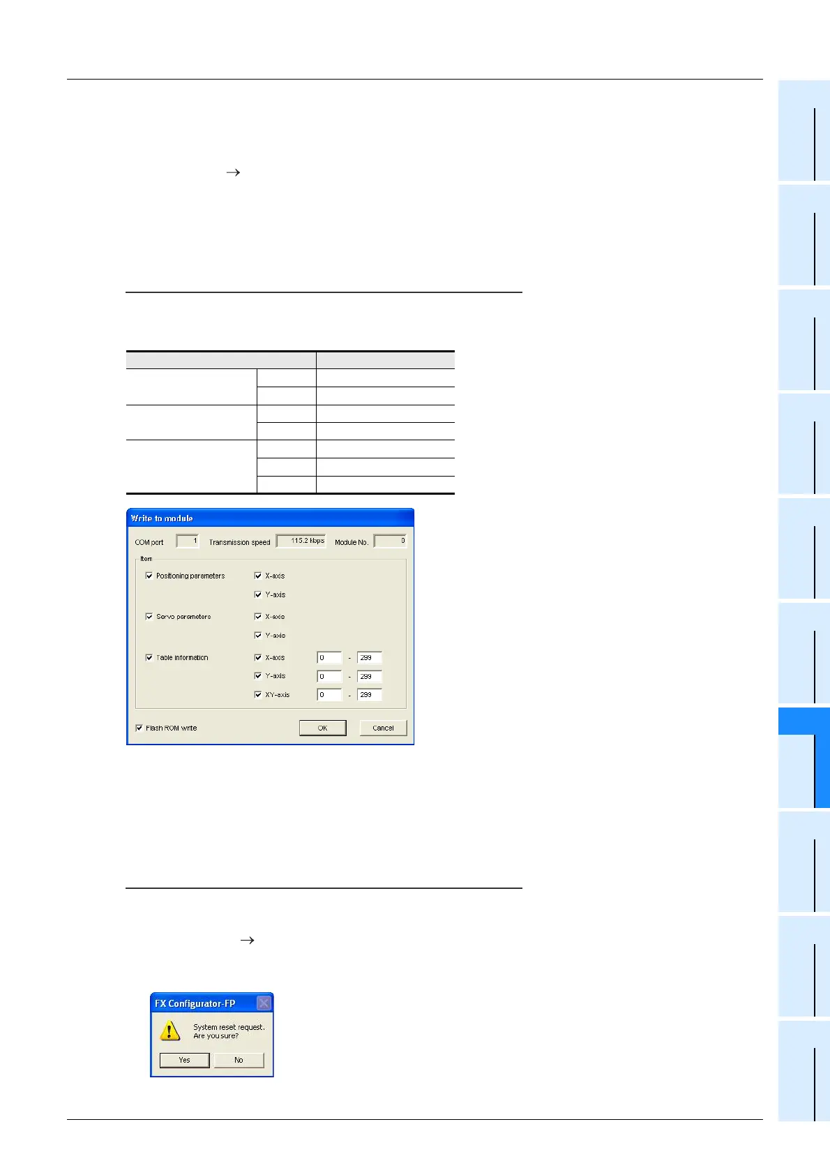
Transferring positioning parameters and servo parameters to the 20SSC-H
(Writing them to the flash memory)
Select [Online] [Write to module].
When the Write to module dialog box appears, select data to be written, and then click the [OK]
button.
Make sure to check the check box "Flash ROM write" here because parameters should be written
also to the flash memory in the 20SSC-H.
Saving parameters to the flash memory
Make sure to save the parameters to the flash memory.
When the power of the 20SSC-H is turned OFF once and then turned ON again, the following data stored in
the flash memory is transferred to the buffer memory.
6 Transferring servo parameters to the servo amplifier
1) Turn OFF the power of the servo amplifier and PLC (including the 20SSC-H).
2) Turn ON the power of the servo amplifier.
3) Turn ON the power of the PLC (including the 20SSC-H).
Transfer method by system reset (20SSC-H Ver. 1.10 or later)
By system reset performed for the 20SSC-H Ver. 1.10 or later from FX Configurator-FP (Ver. 1.10 or later),
servo parameters will be transferred to the servo amplifier.
1) Select [Online] [System reset].
2) When the following message appears, click the [Yes] button to perform system reset.
Click the [No] button to cancel the system reset operation.
BFM number
Positioning parameters
X-axis BFM #14000 to #14199
Y-axis BFM #14200 to #14399
Servo parameters
X-axis BFM #15000 to #15199
Y-axis BFM #15200 to #15399
Table information
X-axis BFM #1000 to #3999
Y-axis BFM #4000 to #6999
XY-axis BFM #7000 to #12999

 Loading...


