5 - 8
5.2 Fail-safe Circuit
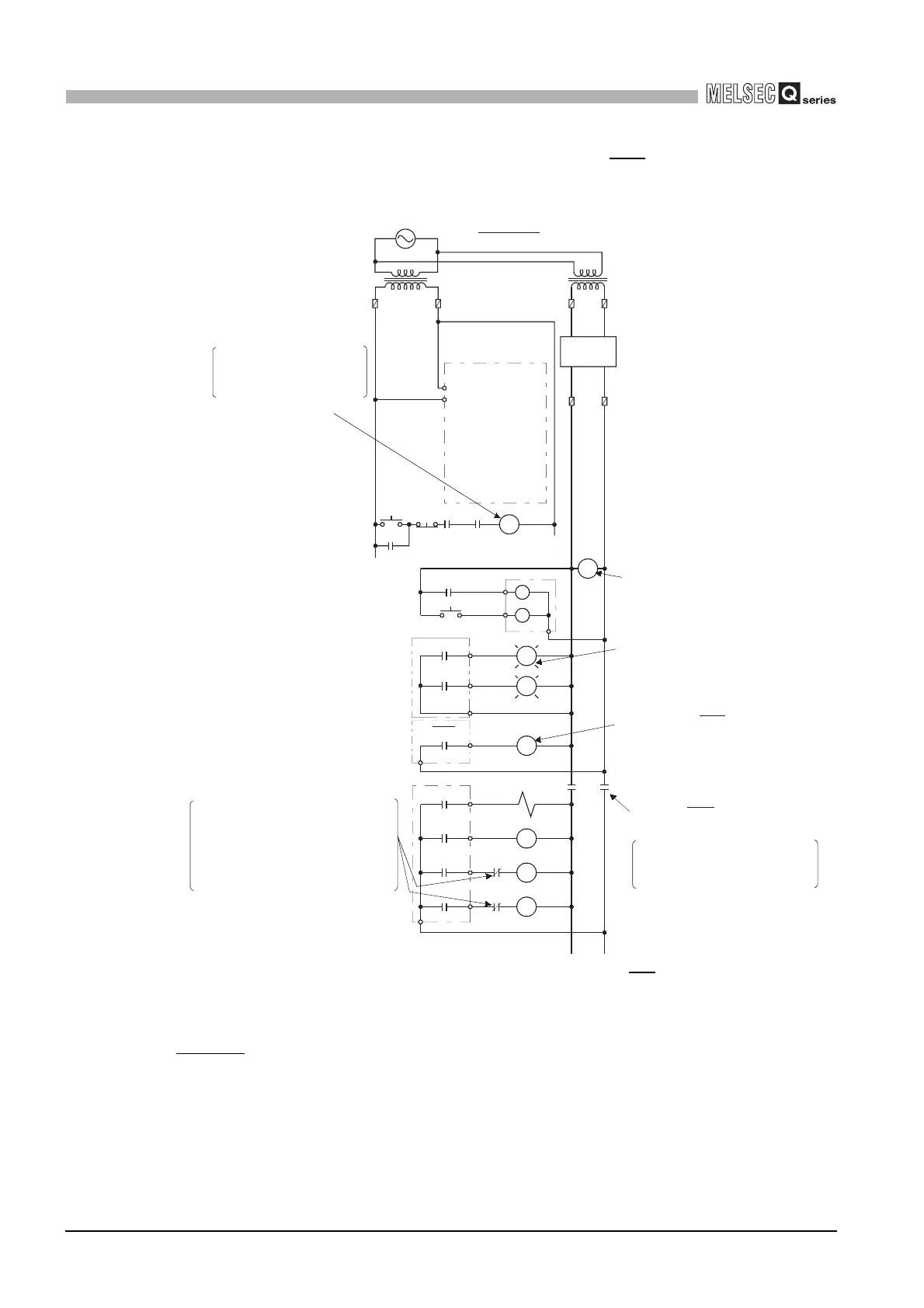
5
SETTINGS AND PROCEDURES BEFORE OPERATION
(2) System design circuit example (when using ERR contact of power
supply module)
Figure 5.4 System design circuit example (when using ERR contact)
The power-ON procedure is as follows:
For AC/DC
1) Turn ON the power.
2) Set the C Controller module to "RUN".
3) When the DC power is established, RA2 goes ON.
4) RA2’s ON turns XM ON, and processing starts in the user program
*1
when the DC input signal is
established 100%.
5) Turn ON the start switch.
6) When the magnetic contact (MC) comes ON, the output equipment is driven by the user program.
RA2
For AC/DC
Power supply
Fuse
Transfor-
mer
Fuse
Transfor-
mer
RUN/STOP circuit
Started when RA1 (control
start output of C Controller
module) turns ON.
START SW
STOP SW
C Controller
module
User
program *1
RA1
MC
RA3
Output module
Ym
L
Yn
RA1
RA3
ERR
Output module
Power supply module
MC1
MC2
MC2
MC
MC1
Provide external interlock circuits for
conflicting operations, such as
forward rotation and reserve rotation,
and for parts that could damage the
machine or cause accidents if no
interlock were used.
Interlock circuit as necessary
MC MC
In the case of an emergency
stop or a stop caused by a limit
switch
Low battery alarm
(Lamp or buzzer)
Turns OFF by ERR due to
stop error
Output by ERR contact OFF
Power OFF of equipment
Voltage relay is
recommended
Fuse
XM
RA2
DC power
(-) (+)

 Loading...


