5
SETTINGS AND PROCEDURES BEFORE OPERATION
5.4 Parts Names and Functions
5 - 19
1
OVERVIEW
2
SYSTEM
CONFIGURATION
3
SPECIFICATIONS
4
FUNCTIONS
5
SETTING AND
PROCEDURES
6
I/O NUMBER
ASSIGNMENT
7
MEMORIES AND
FILES
8
INSTALLING /
UNINSTALLING
* 1 Keep the dummy CompactFlash card in a safe place after replacing it with an actual
CompactFlash card so that it can be used again in the future when the CompactFlash card is
removed.
* 2 Operate the RUN/STOP/MODE switch and RESET/SELECT switch by hand.
Using a screwdriver or any other tool can cause a failure.
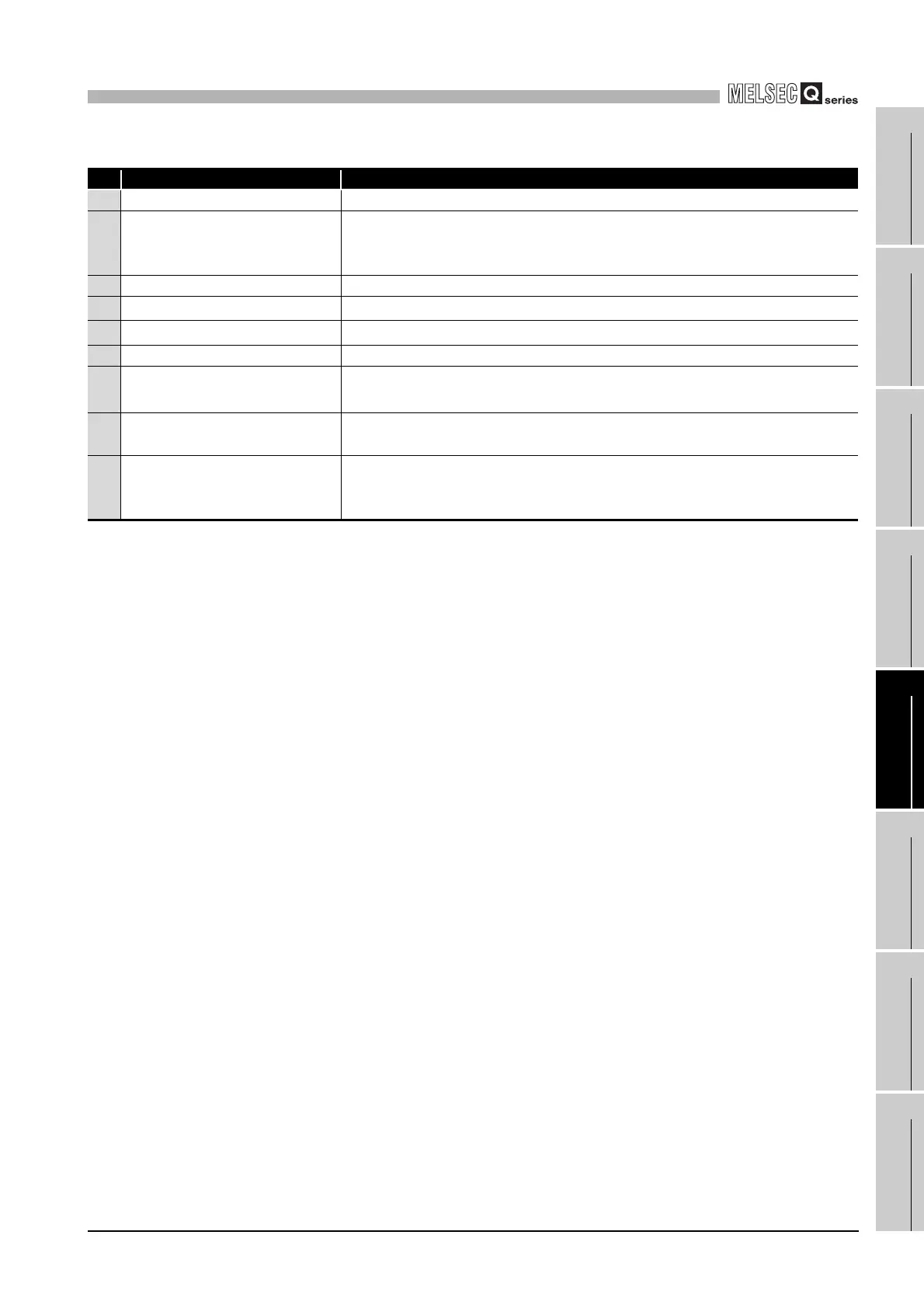
Table5.2 Part names
Name Description
1) Indicator LEDs Refer to this section (1) for the indicator LEDs.
2)
10BASE-T/100BASE-TX interface
connector (RJ45)
Connector used to connect the C Controller module to 10BASE-T/100BASE-TX.
(The C Controller module determines 10BASE-T or 100BASE-TX depending on
the target device.)
3) RS-232 interface connector Connector used to connect the C Controller module to RS-232.
4)
RUN/STOP/MODE switch
*2
Refer to this section (2) for the RUN/STOP/MODE switch.
5)
RESET/SELECT switch
*2
Refer to this section (3) for the RESET/SELECT switch.
6) EJECT button Used to remove the CompactFlash card from the C Controller module.
7)
CompactFlash card installation
slot
Slot used for installing the CompactFlash card into the C Controller module.
(A dummy CompactFlash card is factory-installed.
*1
)
8) Battery
Used for protecting the standard ROM files, and backing up the battery-backed-up
RAM data and the clock data.
9) Battery connector pin
For connection of the battery lead wire.
(The lead wire is shipped disconnected from the connector to prevent battery
consumption.)

 Loading...


