EasyManua.ls Logo

Mitsubishi MELSEC Q Series User Manual

Mitsubishi MELSEC Q Series
664 pages
To Next Page IconTo Next Page
To Previous Page IconTo Previous Page
Page #446 background imageLoading...
Page #446 background image
10 - 45
10.3 Programming Using MELSEC Data Link Functions
10.3.11 Device types for MELSEC data link functions
10
FUNCTIONS AND PROGRAMMING
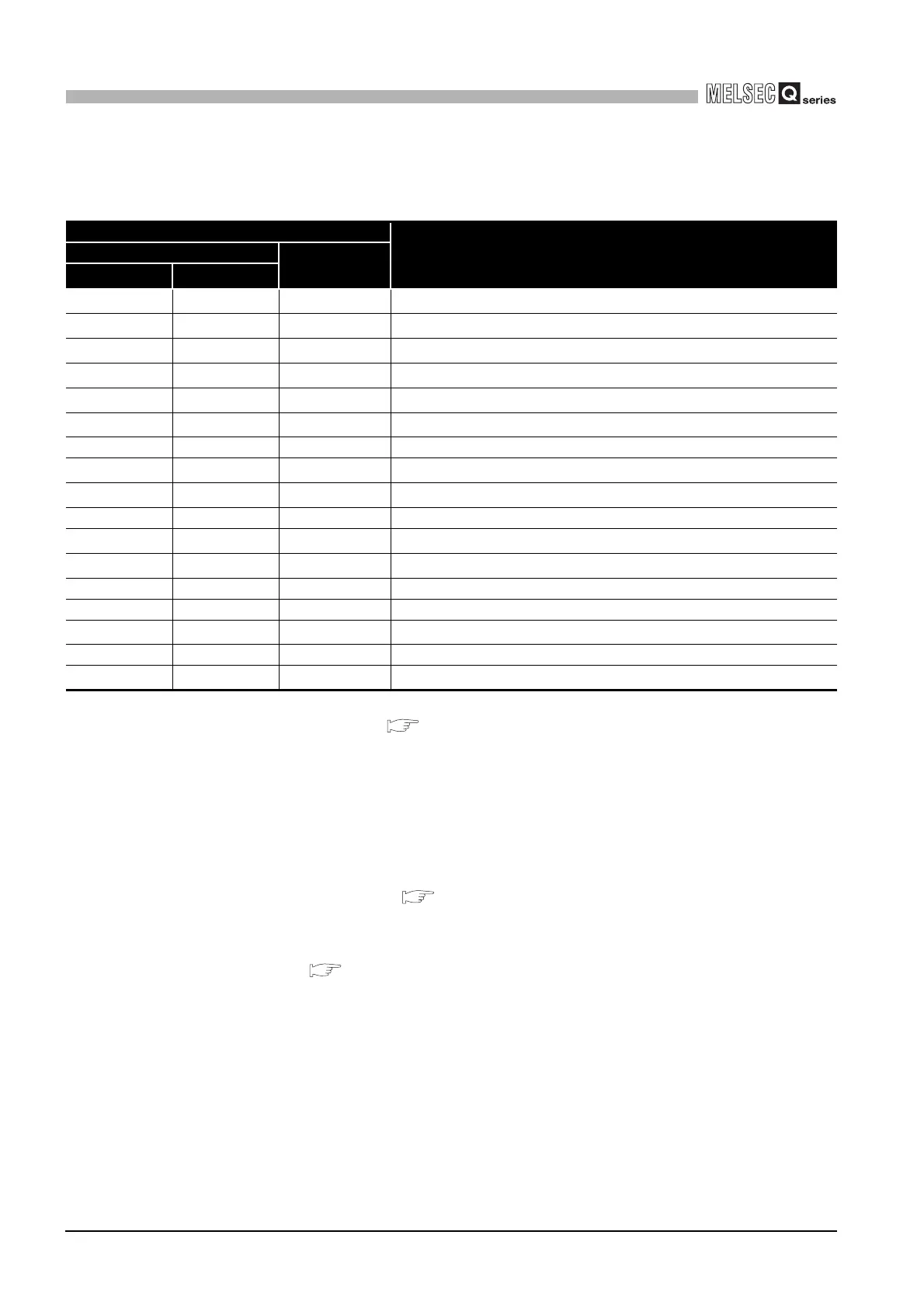
(3) Device types for CC-Link module access
* 1 Device name specification (macro) is defined in the included file "MdFunc.h" of the MELSEC data
link functions. ( Section 10.2.3 (1) )
* 2 Not usable for the mdRandR, mdRandW, mdDevSet and mdDevRst functions.
* 3 The link special relay for CC-Link (own station SB) has two different device type definitions
(DevSM and DevQSB), and either of them may be specified.
* 4 The link special register for CC-Link (own station SW) has two different device type definitions
(DevSD and DevQSW), and either of them may be specified.
* 5 Continuous access to link devices of a CC-Link module (with mdSend, mdReceive, mdRandR,
mdRandW, mdDevSet, or mdDevRst function), for which Block guarantee of cyclic data per
station is enabled, may result in a delay of up to one link scan time. (This is the same as the case
where the QBF_ToBuf or QBF_FromBuf function is used with "automatic" set for the CC-Link
refresh method. ( Section 4.3.1))
Moreover, please note that the function of block guarantee of cyclic data per station cannot be
used in mdRandR and mdRandW function.
Refer to the following for details.
( mdReadR and mdReadW functions in MELSEC data link function HELP)
Table10.16 Device types for CC-Link module access
Device type
Device
Code specification Device name
specification
*1
DEC. HEX.
11H DevX
Own station RX
*5
22H DevY
Own station RY
*5
55H DevSM
Own station SB (link special relay for CC-Link)
*3
14 EH DevSD
Own station SW (link special register for CC-Link)
*4
25 19H DevQSB
Own station SB (link special relay for CC-Link)
*3
28 1CH DevQSW
Own station SW (link special register for CC-Link)
*4
33 21H DevMRB Own station random access buffer
36 24
H DevWw
Own station link register (for sending)
*5
37 25H DevWr
Own station link register (for receiving)
*5
50 32H DevSPB Own station buffer memory
-32768 8000
H DevRBM
Other station buffer memory
*2
-32736 8020H DevRAB
Other station random access buffer
*2
-32735 8021H DevRX Other station RX
-32734 8022H DevRY Other station RY
-32732 8024
H DevRW
Other station link register
*2
-32669 8063H DevSB Other station SB (link special relay for CC-Link)
-32668 8064
H DevSW
Other station SW (link special register for CC-Link)
*2

Table of Contents

Other manuals for Mitsubishi MELSEC Q Series

Questions and Answers:

Mitsubishi MELSEC Q Series Specifications

General IconGeneral
SeriesMELSEC Q Series
TypeModular PLC
Programming SoftwareGX Works2, GX Works3
CategoryProgrammable Logic Controller (PLC)
I/O ModulesDigital I/O, Analog I/O, High-Speed Counter, Positioning
CommunicationEthernet, CC-Link
Programming LanguagesLadder Logic, Structured Text, Function Block Diagram, Sequential Function Chart, Instruction List
MemoryFlash Memory
I/O PointsUp to 4096 points (expandable with additional modules)
Power SupplyAC or DC power supply options available, depending on the base unit and modules.
MountingDIN rail mounting
Operating Temperature0°C to 55°C
Storage Temperature-25°C to 75°C
Humidity5% to 95% (non-condensing)
Vibration Resistance10 to 57 Hz, 0.075mm amplitude
WeightVaries depending on the module, from a few grams to several kilograms.
Shock Resistance147 m/s² (3 times each in X, Y, Z directions)

Summary

CHAPTER1 OVERVIEW

1.1 Features

Describes the features of the C Controller module, including VxWorks, standard ROM, large data storage, and I/O control capabilities.

CHAPTER2 SYSTEM CONFIGURATION

2.1 System Configuration

Explains device configuration, development environment connection, and system configuration overview for C Controller systems.

2.1.1 Devices to be used

Details the base units, extension cables, power supply modules, and other components used with the C Controller module.

CHAPTER3 SPECIFICATIONS

3.1 General Specifications

Provides the general specifications of the C Controller module, including operating ambient temperature, humidity, vibration, and shock resistance.

CHAPTER4 FUNCTIONS

4.1 Function List

Lists the functions of the C Controller module, such as I/O module access, remote operation, and self-diagnostic functions.

CHAPTER5 SETTINGS AND PROCEDURES BEFORE OPERATION

5.1 Handling Precautions

Explains critical handling precautions for the C Controller module, including environment, installation, and connection safety.

CHAPTER6 I/O NUMBER ASSIGNMENT

6.1 Relation between No. of Base Units and No. of Slots

Explains how base units and slots relate to I/O number assignment for the C Controller module.

CHAPTER7 MEMORIES AND FILES HANDLED BY C CONTROLLER MODULE

7.1 Memory of C Controller Module

Explains user memories (Standard ROM, Work RAM, Battery-backed-up RAM, CompactFlash) and system memory.

CHAPTER8 INSTALLING AND UNINSTALLING SW[]PVC-CCPU

8.1 Development Environment

Details the product requirements for the development environment, including personal computer specifications and operating system.

CHAPTER9 UTILITY OPERATION

9.1 Common Utility Operations

Explains common operations for utilities, including starting, exiting, setting connection targets, and displaying help screens.

CHAPTER10 FUNCTIONS AND PROGRAMMING

10.1 Outline of Functions

Outlines bus interface functions and MELSEC data link functions supplied with SW PVC-CCPU for accessing modules and CPUs.

CHAPTER11 OVERVIEW OF MULTIPLE CPU SYSTEM

11.1 What is Multiple CPU System ?

Defines the multiple CPU system concept, explaining how multiple CPU modules work together for enhanced performance.

CHAPTER12 MULTIPLE CPU SYSTEM CONFIGURATION

12.1 System Configuration

Explains system configuration for multiple CPU systems, including device compatibility and connection methods.

CHAPTER13 MULTIPLE CPU SYSTEM CONCEPT

13.1 Mounting Position of CPU Module

Details the mounting positions of CPU modules (C Controller, Basic QCPU, High Performance QCPU, Motion CPU) in a multiple CPU system.

CHAPTER14 COMMUNICATIONS BETWEEN CPU MODULES

14.1 Data Communications by MELSEC Data Link Functions

Explains data communication methods using MELSEC data link functions between CPU modules, including auto refresh and shared memory.

CHAPTER15 PARAMETERS ADDED FOR MULTIPLE CPU SYSTEM

15.1 Parameter List

Lists parameters required for multiple CPU system operation, highlighting setup necessity and consistency checks in the C Controller setting utility.

CHAPTER16 PRECAUTIONS FOR USE OF AnS SERIES MODULE

16.1 Precautions for Use of AnS Series Module

Provides specific precautions for using AnS series modules, including applicable I/O and special function modules and control CPU settings.

CHAPTER18 TROUBLESHOOTING

18.1 Troubleshooting Basics

Provides fundamental steps for troubleshooting, including visual checks, fault verification, and narrowing down the error cause.

Related product manuals