10.6 Safe Torque Off Connections
Management channels, including the "Hardware feedback" of the Safe Torque Off circuit, are controlled
using the X4 (X14) Connector, also referred to as JRC1. Optional circuit delivering a dry feedback
contact can be connected through connector X1-X11.
Both of the monitoring channel modes are always available. It is the user's prerogative to choose
which type of monitoring to use; "Hardware feedback", "Software feedback" or both features
simultaneously.
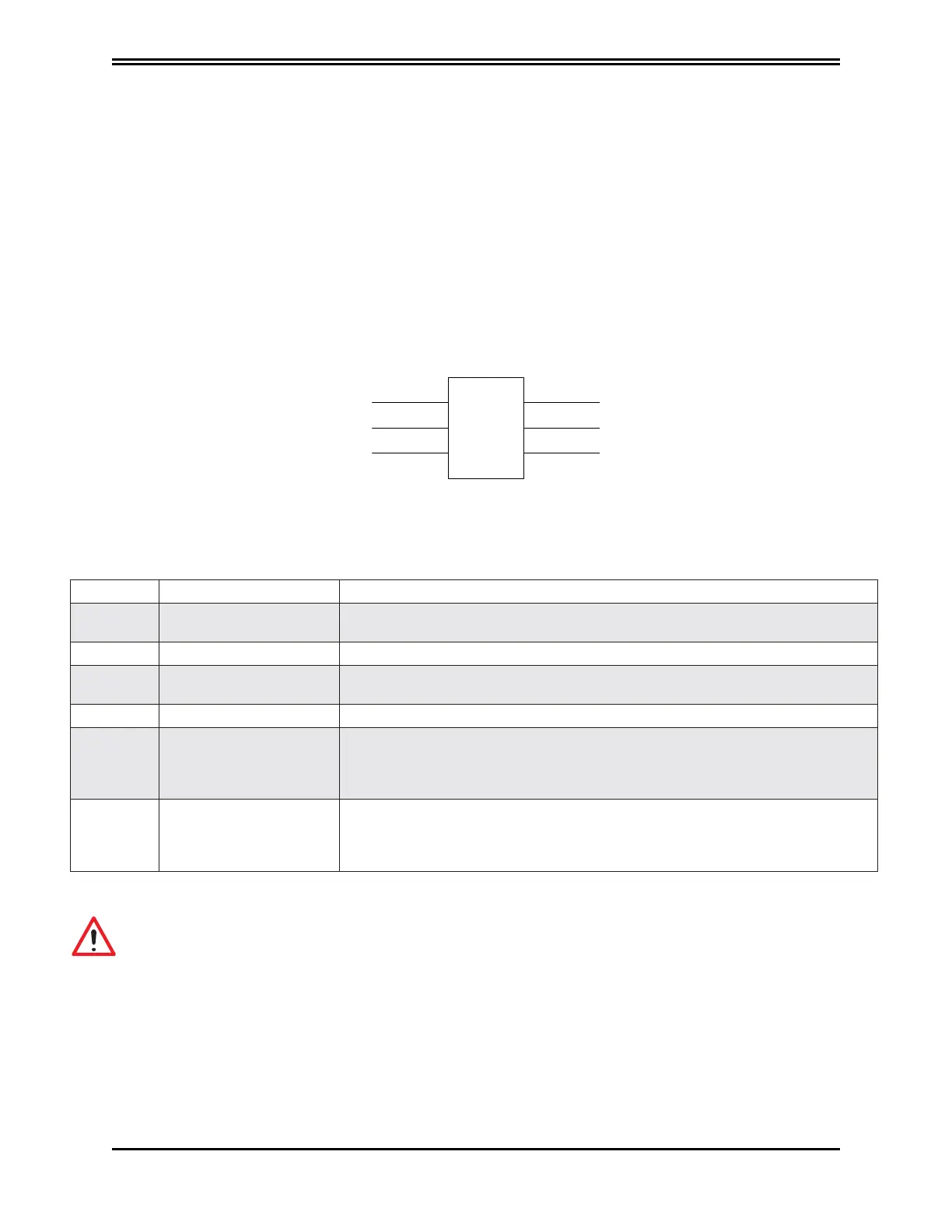
10.6.1 Connector X4 (X14)
The following figure and table describes the connector pinouts: 6 contacts, Weidmüller model B2
3.50 / 06/180 SN BK BX. Note that the drive's power stage cannot start until STO signals are not
active.
Connector
Pinout:
6
Contacts,
Model
B2
3.50
/
06/180
SN
BK
BX
Weidmuller
PN: L-MAM2-E-201
Moog Casella DM2020 Installation and Startup Guide
10.6 Safe Torque Off Connections
Feedback CH 1
0 Volt CH 1
0 Volt CH 2
Feedback CH 2
+24 Volt CH 1
+24 Volt CH 2
STO
X4 - X14
1
3
5
2
4
6
Free-hanging connector pin: 6 contacts, model B2 3.50/06/180 SN BK BX, manufactured by Weidmuller
Pin Name Function
1 + “Channel 1” Input +24Vdc of channel 1. This input must be high (+24Vdc) to power the motor.
When the input is low.
2 - “Channel 1” 0V of Channel 1
3 + “Channel 2” Input +24Vdc of channel 2. This input must be high (+24Vdc) to power the motor.
When the input is low (0V) the motor is not powered.
4 - “Channel 2” 0V of Channel 2
5 Testing “Channel 2” Feedback Channel 2. With Channel 2 high (+24Vdc), this output is high, at +3.3Vdc
with reference to pin 4. When Channel 2 is low (0V), this output is low (0V), when
it is high, output is high again. The external testing system must check the
plausibility of this low and high test signal.
6 Testing “Channel 1” Feedback Channel 1. With Channel 1 high (+24Vdc), this output is high, at +3.3Vdc
with reference to pin 2. When Channel 1 is low (0V), this output is low (0V) and
when it is high, output is high again. The external testing system must check the
plausibility of this low and high test signal.
WARNING
In order to be validated according to categories 1 to 4, on the basis of safety principles in UNI EN ISO 13849-2:2008,
table D.2, external cables that run into the JRC1 connector must have shields connected to the earthing circuit
WARNING
To avoid common causes of failure, the “Channel 1” cable (at pins 1, 2 and 6 of JRC1) must be separate from the
“Channel 2” cable (at pins 3, 4 and 5 of JRC1) during installation
WARNING
To prevent short circuits between the input and the test signal, the multi-strand cables of the two channels must
terminate with a cable terminal or other appropriate device
WARNING
The test signal wiring of the two channels must be protected from short circuits to voltage sources; external voltage
must never be applied to the test signal, not even in the case of failure
 Loading...
