PN: L-MAM2-E-201
Moog Casella DM2020 Installation and Startup Guide
4.3 UL
4.3. UL
4.3.1 REQUIREMENTS
• The “modular servo-drive Systems – DM2020 series”, Specifically servo-drive systems which use a
common “power supply (AC/DC converter)” to “multiple modules (power inverters)”, are intended
exclusively for application with each other. The UL certification does not cover “standalone power
supplies (AC/DC converters)” or “modules (power inverters)” supplied by other “power supply (AC/DC
converter)” (different models or manufacturer).
Short-circuit protection
• “The power supply model no. PS-S and PS-M are suitable for use on a circuit capable of delivering not more than
5000 RMS symmetrical amperes, 480 V AC +10% maximum”, when protected by the external (recommended)
semiconductor fuse type as per the following table”
• “The power supply model no. PS-L is suitable for use on a circuit capable of delivering not more than 10,000 RMS
symmetrical amperes, 480 V AC +10% maximum”, when protected by the external (recommended)
semiconductor fuse type as per the following
table”
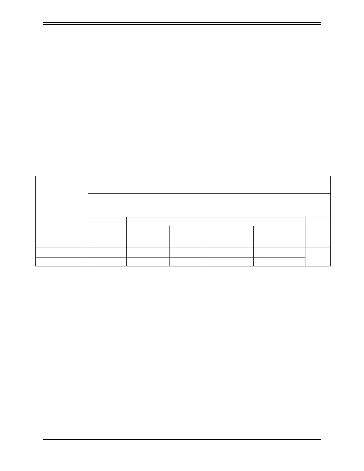
External (recommended) semiconductor fuses
Power supply
(converter)
Model no.
R/C fuses manufactured by
Bussmann Div Cooper (UK) Ltd
(200 kARMS Symmetrical A.I.C.)
Mod. no.
Ratings
Qty
Current
ARMS
Peak
let-through
current
I2t
@480 V
A2sec
V AC
CC201(L50) 160 FEE 160 2142 5218 690
3
CC202(L150) 315 FM 315 6000 60820 690
Please note: The brushless AC motor servo drives “DM2020 series” may be protected by any equivalent UL listed
(JDDZ) or UL recognised external semiconductor fuses (JFHR2). These fuses must have the same ratings as the
above fuses evaluated during the short circuit test and in particular with “peak-let-through current Ip” and “clearing
I2t” equal or lower than tested fuse.
Wiring
• This equipment is suitable for factory wiring only; the terminal blocks and the connectors for power
connection wiring are not suitable for ield wiring.
• The wire connectors shall be any listed (ZMVV) or R/C wire connectors and soldering lugs (ZMVV2), used with
60 °C/75 °C copper (CU) conductor only, within electrical ratings and used with its appropriately evaluated
crimping tool.
• The wiring terminals shall be used with the tightening torque values specified in this manual.
• In particular the “power supply (converter)” and “modules (inverters)” interconnection wiring shall be obtained
only with the DC bus terminal blocks and with the DC bus interconnection bars, made with close eyelet wire
terminals. These particular DC bus wiring components are provided by the manufacturer and described in this
manual.
 Loading...
