PN: L-MAM2-E-201
Moog Casella DM2020 Installation and Startup Guide
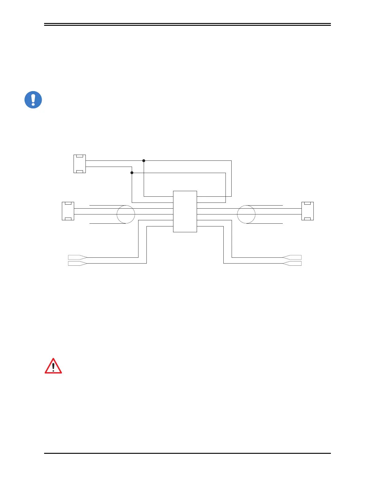
5.3.6.5 Signal Connection
X18 - X19
0 Volt
Shielded cable
1
1
2
3
5
7
9
11
2
4
6
8
10
12
+ 24 Volt
5.3.6.5 Signal Connection
For more details on signal connectors X5, X15, X6, X16, see
Layout of connectors and other interfaces
on the axis module
section
5.3.6.6 Motor Cable Connection Details
The following figures show the motor cable connection points. For the motor cable
specifications, see
Cables
section.
CAUTION
While defining the brake connections, consider the potential for a drop in voltage for connections over 10 m with
cables that do not have an adequate cross-section
MISE EN GARDE
En définissant les connexions de frein, envisager la possibilité d'une chute de tension pour les connexions de plus de
10 m avec des câbles qui ne dispose pas d'une section suffisante
24 Volt Power Supply
Motor Brake 1
Term_2
Term_2
Brake command
Motor Brake 2
1
2
1
2
Term_1
Term_1
If the power supply cables of the brake are
in the power supply cable of the motor,
separate shieldings must be foreseen
If the power supply cables of the brake are
in the power supply cable of the motor,
separate shieldings must be foreseen
• Power must be supplied externally (on pins 1 and 2 with a 24 Volt connection, and on pins 3 and 4 with a 0 Volt
return).
• Overload protection is provided with a delayed fuse (maximum 4 A), to protect both internal devices and the
power supply, to be installed externally on the 24 V line if not otherwise protected.
• The interface manages currents from 2 A to 24 V.
• The internal devices are protected from short circuits between the terminals (between 5 and 7 and between 6
and 8) and to earth.
• The drive identifies whether the command has been executed correctly along with any short circuit
conditions, reported as an absence of output on terminal 5 (6 for axis 2).
• The same connector has an input for a motor protection thermal sensor, with the same characteristics as
the sensor on position feedback connectors (X1-X2 and X3 etc.).
WARNING
In the absence of an external power supply, the power to the brake is taken from the drive.
AVERTISSEMENT
A défaut d'une alimentation externe, la puissance du frein est prise de l'unité.
The figure shows the functional and time relations between enabling, activation signal and velocity command. Motor
brake times vary depending on the motor models, and reference shall be made to motor model data.
The external brake activation command must reach the drive when the motor speed is close to or equal to 0. The delay
introduced by the drive between receiving the command and its transmission to the brake is less than 125 us. The
delay in brake activation depends on the type of brake and is specified by the motor manufacturer.
 Loading...
